In this month’s Schaeffler INA belt focus, Tim Adams, Schaeffler REPXPERT technical trainer and belt system specialist, runs through a timing belt installation on the popular Iveco Daily 111/Fiat Ducato 2.3 Diesel engine.
This engine has been used for many years, and it has always been recommended that a new water pump is installed at the same time as carrying out a timing belt system replacement. It is also considered best practice to replace the auxiliary belt (two in this instance) and all associated auxiliary system parts, as they need to be removed to access the timing belt drive. This particular unit has been in constant service from 2002 up to the present day and the expected labour time for this repair is 4.2hrs.
It is important to remember to advise vehicle owners that the FEAD belt system will have covered the same mileage as the timing belt drive, so will have been subjected to the same amount of usage and wear. Of further note is that the air conditioning drive belt has to be cut to be removed and therefore cannot be reused.
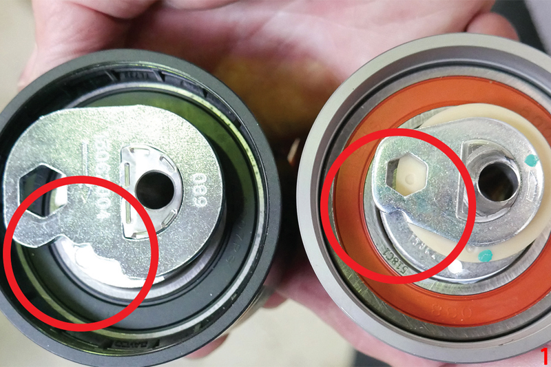
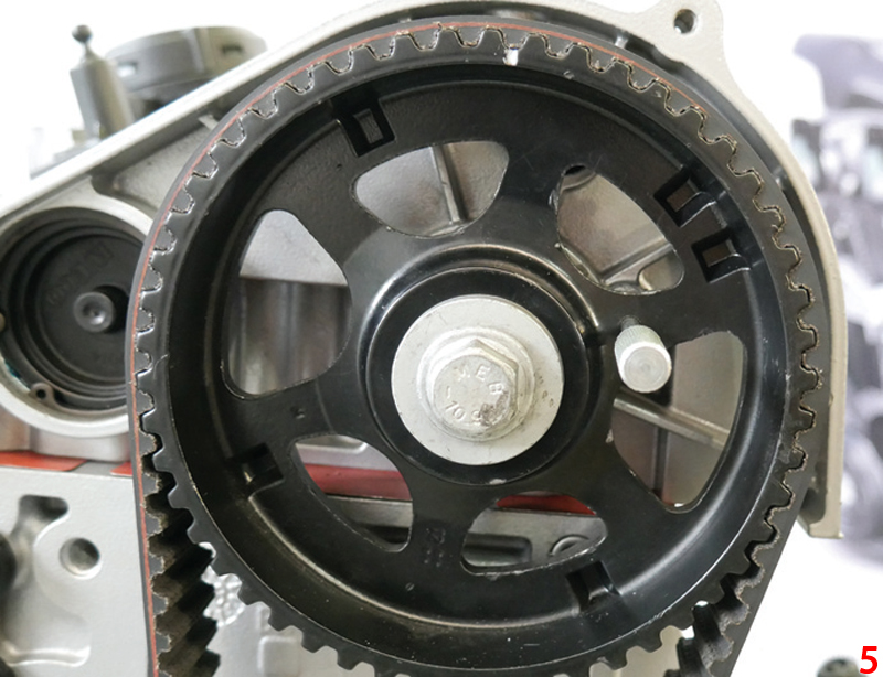
There are two different OE tensioner designs which have been fitted to this engine during its lifespan. Both are completely interchangeable, but it is essential that the correct set up instructions are used for the specific tensioner design that has been supplied. To identify the type of tensioner, the obvious visual differences are the number of cutouts on the installation eccentric plate.
The tensioner pictured on the left in Fig.1/main image has three notches on the eccentric plate, the tensioner on the right has just one.
Step-by-step guide
It is essential that the engine is left to cool to ambient (room) temperature before carrying out this repair, to ensure that no anomalies occur during tensioning. Allow approximately four hours for this, following the first of our “4T” principles: Temperature, Tools, Torque & Tension.
Raise and support the front of the vehicle, then remove both front wheels, wheel arch liners and undershield. Drain the cooling system. Remove both headlamps, radiator grille, front bumper, bonnet release cable and lock and bonnet shut panel. Next remove the cold air intake pipe, AC condenser from the radiator (if fitted). Do not disconnect pipes.
Disconnect the coolant expansion tank multi-plug before removing the radiator and intercooler assembly. Remove both auxiliary drive belts, viscous fan, tensioner and idler. Slacken and tilt the alternator (the upper bolt will also need to be removed).
Support the engine and remove crankshaft pulley bolts and pulley, along with the timing belt cover (check for any damage to the cover). Now remove the camshaft cover blanking plugs along with the blanking plug from the cylinder block.
Note: During the installation process keep a sharp lookout for any oil or coolant leaks and double check that the timing cover is free from damage.
The next of our 4Ts is Tools. Always use the correct engine locking tools.
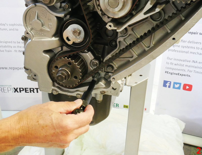
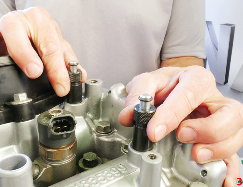
Turn the crankshaft to just before TDC No 1 cylinder and fit the crankshaft locking pin tool 99360615 (Fig. 2). Turn the crankshaft clockwise until it stops against the locking pin. Insert both camshaft locking pins tool 99360614 (Fig. 3).
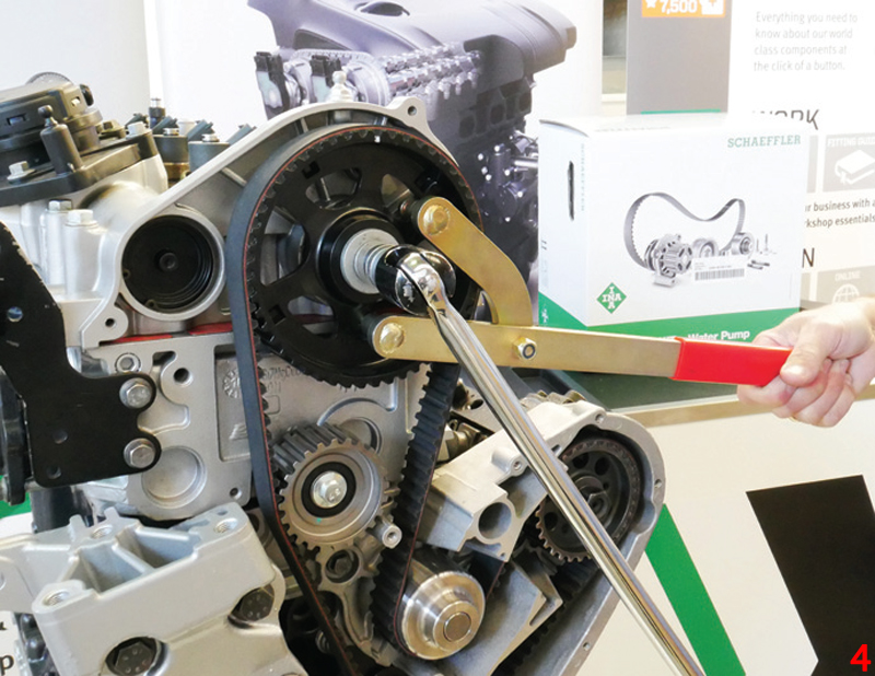
Slacken the timing belt tensioner pulley bolt and move the tensioner away from the belt, then lightly tighten the bolt and remove the timing belt. Install a new water pump. Check that the camshaft and crankshaft locking tools are located correctly. Using a counterhold tool (Fig. 4), hold the camshaft sprocket (do not rely on camshaft locking tools alone, as damage could be caused to the camshafts). Release the sprocket until it rotates freely without tilting.
Using a locking pin tool 99360608, locate the sprocket at the three o’clock position (Fig. 5).
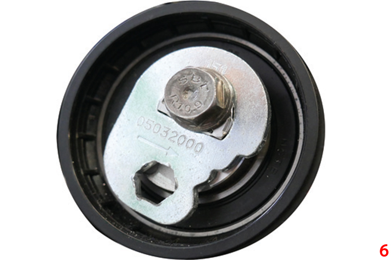
Loosen the tensioner bolt and, using an Allen key, rotate the installation eccentric plate to the position shown in Fig. 6 before fitting a new belt, aligning any timing belt marks (if present) on camshaft and crankshaft sprockets. Then remove camshaft sprocket locking pin and slacken the tensioner bolt.
Three-notch Tensioner Setup
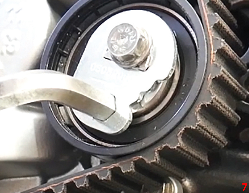
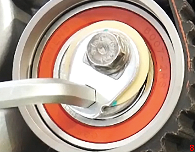
Step 1 Using an allen key, rotate the tensioner installation eccentric anti-clockwise until the left hand notch aligns with the dot on the tensioner body (Fig. 7). Tighten tensioner bolt to 36Nm (±4Nm). This is the third of our 4T principles: Torque.
Step 2 Counterhold the camshaft sprocket and tighten bolt to 130Nm, then remove the crankshaft and camshaft locking pins and rotate the engine in the direction of rotation for eight full revolutions.
Note: Don’t allow the crankshaft to rotate anti-clockwise.
As before, on the last revolution bring the crank up to just before TDC and fit the crankshaft locking pin. Turn the crank until it touches against the pin. Ensure the camshaft locking pins can be easily inserted. If not, repeat the installation procedure.
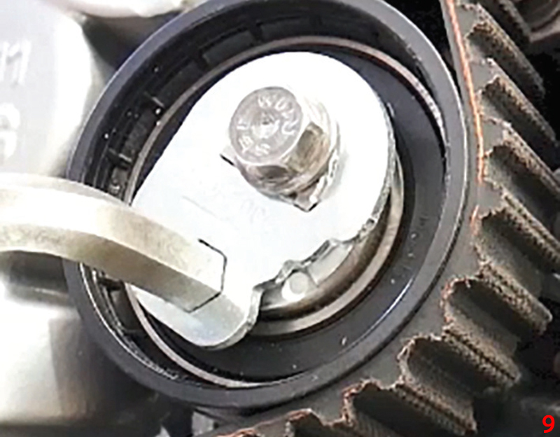
Step 3 Slacken the tensioner bolt and use an Allen key to turn the tensioner until the central notch window aligns with the dot on the tensioner body (Fig. 9). Tighten bolt to 36Nm (±4Nm). This should correctly tension the belt – the final 4T principle.
Step 4 Remove the camshaft and crankshaft locking pins and rotate the engine in direction of rotation for two full revolutions until just before TDC and insert crankshaft locking pin. Turn the crankshaft clockwise until it touches the pin. Ensure the camshaft pins can be easily inserted. If not, repeat the tensioning procedure.
Remove the locking tools and reinstall all components in reverse order and tighten crankshaft pulley bolts to 30Nm.
Fill and vacuum bleed the cooling system using new coolant in accordance with the vehicle manufacturer’s specifications and recommendations. Always carry out a full road test to ensure the heater works correctly and the coolant level remains steady.
One-notch Tensioner Setup
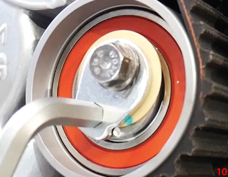
Step 1 Turn Allen key anti-clockwise until the single notch goes past the white dot and covers it completely (Fig. 8), which is the high-tension position.
Step 2 See Three-notch Tensioner Setup.
Step 3 Now turn tensioner clockwise to reveal the dot in the notch window (Fig. 10), which is the nominal position.
Step 4 See Three-notch Tensioner Setup.


