
In this month’s Schaeffler LuK Clutch Clinic, REPXPERT Alistair Mason is replacing the clutch in a 2014 Range Rover Evoque 4X4 that is fitted with a 2.2 D engine and has covered just over 56,000 miles. The owner has reported that the clutch appears to be “slipping”, and a short road test confirmed the problem and clutch replacement was authorised.
Workshop equipment
- Vehicle lift
- Transmission jack
- Engine support
- Clutch alignment tool
- Advised – driveshaft to hub removal tool.
Scheduled repair time:
6.4 hours.

Gearbox removal
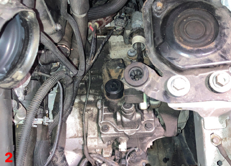
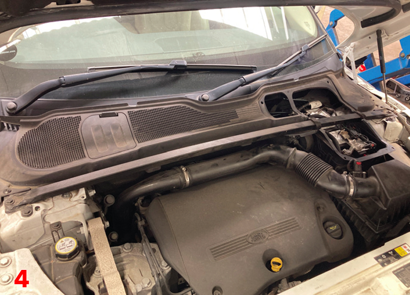
With the vehicle placed on the vehicle lift, open the bonnet and remove the battery cover (Fig.1), air intake duct, front suspension cross brace, plenum chamber cover, battery and battery carrier. With access now available to the gearbox (Fig.2), remove the gearbox multiplugs, starter motor bolts, and ease the starter motor away from the bell housing, securing it in a rest position. Whilst in this area, remove the upper bell housing bolts, disconnect the hydraulic hose connection at the concentric slave cylinder (CSC) and plug hose connection to stop the fluid running out, also disconnect both gear change cables and stow in the bulkhead area.
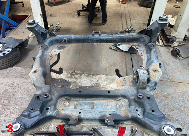
Raise the vehicle lift to waist height, remove both front wheels and the N/S wheel arch liner, then raise the vehicle lift to gain access to the underside, remove the engine and gearbox undertrays and then drain the gearbox oil. Now remove the front subframe (Fig.3), which gives good access to the running gear that needs to be removed. So, remove both front driveshafts and centre support bearing (Note – a special removal tool may be required to push the driveshaft out of the hub assembly), followed by the air charge pipe (Fig.4), disconnect the front prop shaft joint from the transfer box by removing the six bolts and remove the lower pendulum/torque mounting.
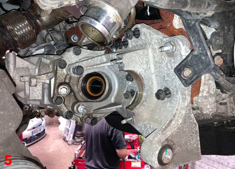
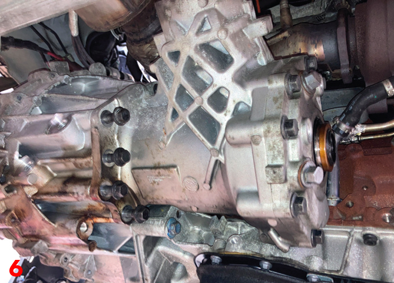
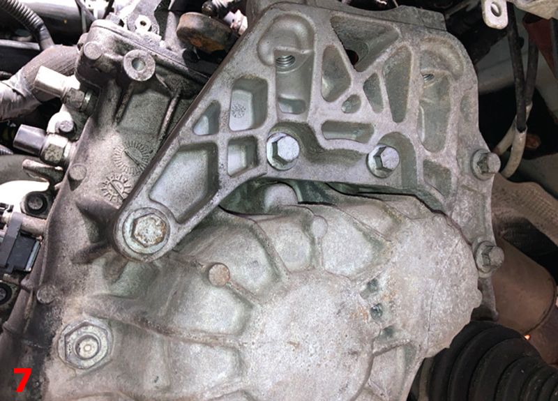
Remove the transfer box/driveshaft centre support bracket (Fig.5) and then unbolt the transfer box from the gearbox (Fig.6), remove the transfer box and then remove the lower bell housing bolts (Note – leave two easily accessible bolts to support the gearbox until the time of removal.) Support the engine using either an engine support or a second transmission jack, gain access to the engine bay and remove the N/S gearbox mounting, lower the engine and gearbox slightly and remove the N/S gearbox mounting bracket (Fig.7). Support the gearbox with a transmission jack, remove the remaining bell housing bolts and ease the gearbox away from the engine, when clear, lower the transmission jack and remove the gearbox.
Fault diagnosis and clutch replacement
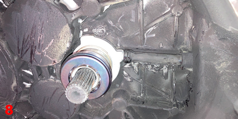
With the gearbox removed, it was clear to see that the clutch had been slipping badly as a lot of the clutch lining material was deposited in the bell housing and the release bearing on the CSC was blue in colour indicating constant contact and over-heating (Fig.8).
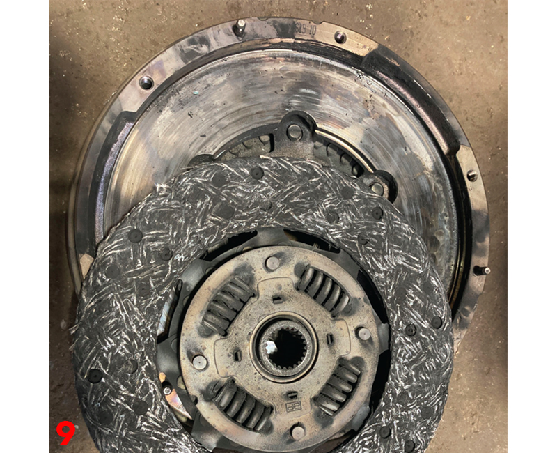
Remove the clutch assembly from the flywheel by unscrewing the six bolts (at this point we could see that the clutch lining had been subjected to a lot of heat as it was starting to break up and that the flywheel face was also “blued” (Fig.9). Due to the flywheel being subjected to excessive heat, replacement of the dual mass flywheel (DMF) was also advised, and the authorisation given.
After obtaining the torque values from Schaeffler’s REPXPERT, degrease the face using brake and clutch dust cleaner, and replace the DMF. Then turn your attention to the gearbox.
First remove any clutch dust (in this instance we used an industrial vacuum cleaner!) and the old CSC and then clean the bell housing using brake and clutch dust cleaner. Mount the new CSC and carefully tighten the bolts and torque to the manufacturer’s specification.
Apply a light smear of high melting point grease to the clutch plate splines on the gearbox input shaft and then mount the clutch plate onto the input shaft and move back and forth, this will ensure the clutch plate is of the correct fitment and evenly distribute the grease. Then remove the clutch plate and wipe off any excess grease.
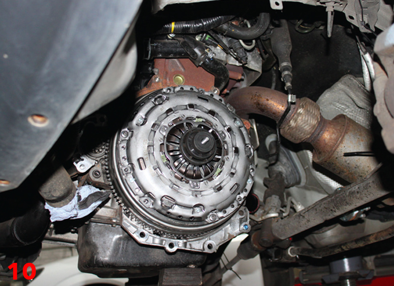
Now mount the new clutch onto the DMF, using a clutch alignment tool to position the clutch plate onto the DMF, ensuring the clutch plate is the correct way around as indicated by “Gearbox side”. Degrease the face on the clutch pressure plate and then install the pressure plate onto the DMF making sure it locates on the alignment dowels (Fig.10). Insert the six bolts, tighten them in an even and sequential process and then torque to the manufacturer’s specification.
Ensure all cables and hoses are clear of the bell housing area, so not to interfere with the gearbox installation and check that the engine to gearbox alignment dowels are correctly installed.
Gearbox installation
Position the gearbox onto the transmission jack and offer it up to the engine, but before rushing, it is always worth spending a little time aligning the gearbox correctly before mounting it onto the clutch and bolting to the engine. So, ease the gearbox into position and, when fully located onto the dowels, insert a couple of accessible bolts and tighten. Raise the engine and gearbox into position and secure with the installation of the N/S gearbox mounting. Refit all the other components in reverse order of their removal and torque all bolts as required to the manufacturer’s specification, not forgetting to replenish the gearbox oil. After the battery lead has been reconnected, reset all electrical consumers and carry out a full road test to ensure that the repair has been successfully completed.


