Blue Print offers its insight into the Toyota Prius Generation 3 brake system.
The Toyota Prius introduced in 1997, was the first full hybrid mass-produced car. Toyota have sold over 15 million hybrid vehicles globally since this date. With each model, comes evolution that affects each model mechanically and technically. In 2009, Toyota/Lexus changed the braking system fitted to the common Prius, Yaris, Auris/Corolla and CT200h models.
The brake system fitted to the Generation 3, Toyota Prius is different to a conventional hydraulic brake system and requires some background knowledge, before working on the system.
There are some commonalities between the old system fitted to the previous model Prius and the new system, but there are some fundamental differences that are definitely worth knowing. As with conventional brake systems, the brake fluid replacement is part of the vehicle’s routine maintenance schedule, due to the hygroscopic nature of brake fluid. Therefore, this information is important when servicing or maintaining a Toyota or Lexus Hybrid vehicle.
The Hybrid System
In an ICE vehicle, fuel is used to increase road speed and then when pressure is taken off the accelerator, engine braking slows us down. Alternatively, the brake pedal is pressed, which applies the brake pads against the brake discs, which then creates friction and slows the vehicle down.
However, in a hybrid vehicle, the braking system is an integral part of the vehicle’s hybrid system. Fuel is used to accelerate to a speed and then when pressure is taken off the accelerator, the engine is disconnected from the drivetrain and the motor generator in the transmission generates electricity, to charge the high-voltage battery. This ‘regeneration’ is designed to cause the same rate of retardation as engine braking.
Slight pressure of the brake pedal simply increases the rate of charge and therefore the vehicle’s retardation, and it’s only when the driver’s demands on the braking system exceeds what the motor generator can provide, (about 30 per cent braking efficiency) that the hydraulic system comes into action.
The effect of this does two things; it improves your fuel consumption by around 60 per cent and increases the wear life of the brake friction components, with front brake pads normally lasting around 100,000 km/60,000 miles or more.
A downside to this is that the brake calipers/sliders/pads are more prone to seizing through lack of use, especially if they are not inspected during routine maintenance.
So how does the system work?
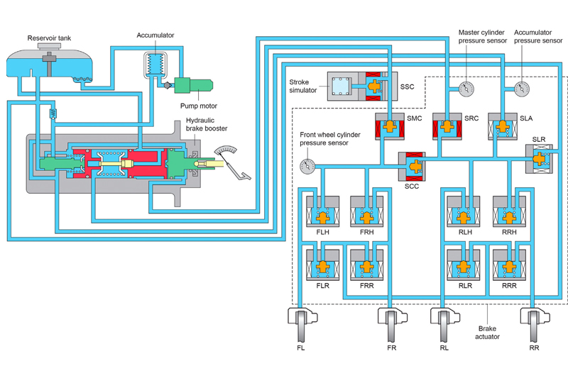
The hydraulic braking system consists of:
- An electrically driven pump and nitrogen filled accumulator to provide the operating pressure for the system.
- A hydraulic brake booster, which controls the pressure relative to the driver’s demand.
- A stroke simulator, which allows the brake pedal to stroke.
- An active wheel speed sensor fitted to each wheel.
- A brake pedal stroke sensor, which monitors pedal movement.
- A hydraulic brake actuator (inside the dotted lines), containing 11 solenoid valves and two Pulse Width Modulated (PWM) linear valves.
So how does the system work?
The brake booster modulates the pressure in the brake line that goes to the SRC valve, which is closed with the system active, (shown when the field coil is red). The stroke simulator provides a degree of movement of the brake pedal by allowing brake fluid to displace the stroke simulator piston, when the brake pedal is pressed. Information from the pedal stroke sensor and master cylinder pressure sensor, about how far and how fast the brake pedal is pressed, and the pressure generated, is relayed to the brake electronic control module (ECM) and from the preprogrammed software in the ECM, a braking strategy is decided. Initially a small pressure is applied to the brake calipers, when the brake pedal is pressed. This is to precondition the brake discs and pads and to prevent the build-up of an oxide layer on the discs or water if driving in wet conditions.
Regenerative braking
Regeneration occurs when the hybrid control unit allows current to flow from the motor generators to the battery. The system is designed to recover as much energy as possible. A combination of regenerative and hydraulic braking is used when the driver’s demand exceeds that, which can be provided by regeneration alone. Brake application is controlled by the two linear valves SLA (apply) and SLR (release) by using a balance of modulated current (PWM) to the valves, the pressure in the calipers can be controlled to produce the desired braking effect.
This system allows for the electronic control of the brakes to be independent of, but relative to, the drivers pedal application. The system also incorporates strategies for electronic brake distribution (EBD), the antilock braking system (ABS), Traction Control (TRC) and vehicle stability control (VSC).
ABS
The solenoid valves FLH and FLR control the pressure and flow to the front left caliper. In the event of a wheel slowing down as if to lock under braking, FLH (Front Left Hold) will be closed to prevent increasing pressure to the front left caliper and should the wheel then lock, FLR (Front left Release) will open, to release the pressure from the caliper to the reservoir allowing the wheel to turn; this action is repeated in quick succession until the wheel behaviour returns to normal. All four wheels can be controlled like this.
VSC/TRC
Controlling the hold valves will isolate parts of the circuit. Individual brakes can then be applied independently of the driver. TRC relies on being able to apply the brake of the driven wheel, which has lost traction under acceleration so as to apply drive to the opposite wheel across the differential. VSC works by applying the brakes to different wheels to correct excessive yaw caused by oversteer or understeer situations. Both systems also take control of the drive torque by controlling the engine throttle or drive motor.
Fail safe
In the event of an electrical failure, the valves revert to their un-energised position. SSC, SCC will close, conversely SMC and SRC will open. This allows a clear passage from the master cylinder to the front brakes, the pressure being generated by the driver pushing on the brake and pressurising the centre section of the brake booster.
Brake bleeding for routine maintenance
This has to be carried out using a suitable diagnostic tool and with an assistant. Due to the complexity of the system, the procedures must be strictly adhered to. There are two bleeding procedures; one for normal bleeding such as regular maintenance or after the replacement of a calliper or brake hose; and one for situations that will have involved letting air into the brake booster.
It is very important to follow the procedure lead by the software in the diagnostic tool; any deviation will cause the system to fail and the hybrid system to go into an emergency mode, logging fault code. ‘C1214 hydraulic control system malfunction’.
At the end of the process, the accumulator pressure is raised and lowered six times whilst the brake ECU opens and closes the internal valves in a sequence to circulate fluid.
If the brake booster, stroke simulator, hydraulic brake actuator, pump, accumulator or any of the pipes are to be replaced or if by accident air has entered the components mentioned, the second procedure is used. This procedure includes bleeding of the stroke simulator and initialisation of the linear valves.
Blue Print offer an extensive range of brake components for hybrid and electric vehicles which are fundamental to vehicles brake system, to decelerate and stop the vehicle. Its range focuses on meeting or exceeding ECE-R90 requirements, by lowering noise and vibration as well as reducing dust and emissions. This is done by using friction material, which contains less harmful metals such as copper.


