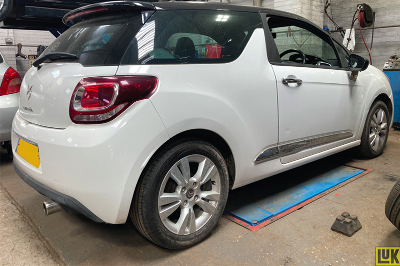
In this month’s Schaeffler LuK Clutch Clinic, REPXPERT Alistair Mason is replacing the clutch in a 2014 Citroën DS3 fitted with a 1.2 VTi engine. The vehicle has covered a little more than 55,000 miles and the owner has reported that the clutch appears to be “slipping”.
Vehicle Information
Manufacturer: Citroën
Model: DS3
Year: 2014 Engine 1.2 VTi
Mileage: 55,000
Schedule time: 5.75 hours
Gearbox removal
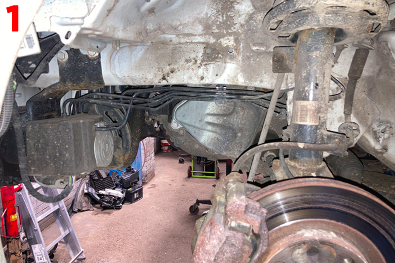
With the vehicle positioned on the lift and the bonnet opened, disconnect the battery, and then raise the vehicle lift to gain access to the underside, to remove the engine undertray and then drain the gearbox oil. Whilst the oil is draining remove both front wheels, both driveshaft nuts and the N/S/F wheel arch liner (Fig.1).
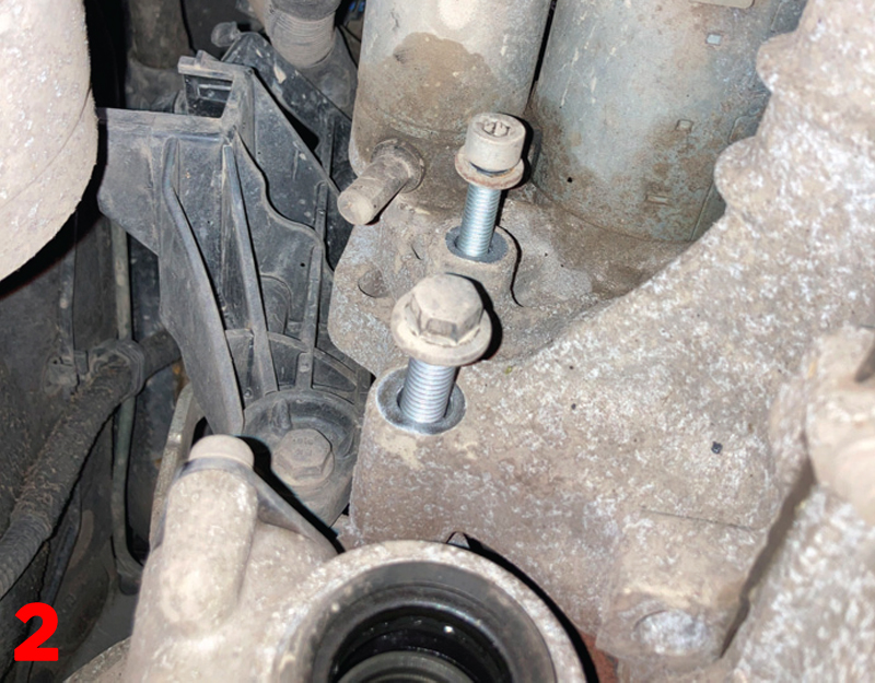
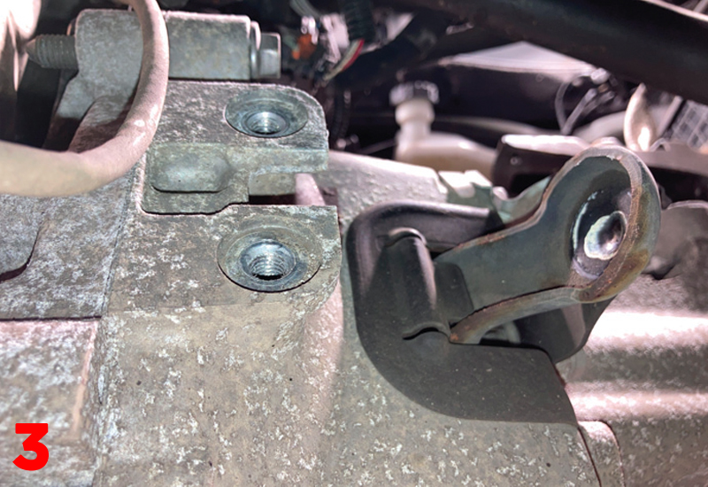
Remove both bottom ball joint pinch bolts and lever the bottom arms down to remove the bottom ball joints from the hub assemblies, ease the outer CV joints out of the hubs and then lever both driveshafts out of the gearbox and remove from the vehicle. Refit the gearbox oil drain plug and tighten, then remove floor brace/strengthening bar and the lower bell housing bolts, but leave two easily accessible bolts to support the gearbox until its removal. Remove the lower gearbox mounting, the exhaust front pipe mounting, starter motor bolts (Fig.2) and then the clutch slave cylinder (Fig.3).
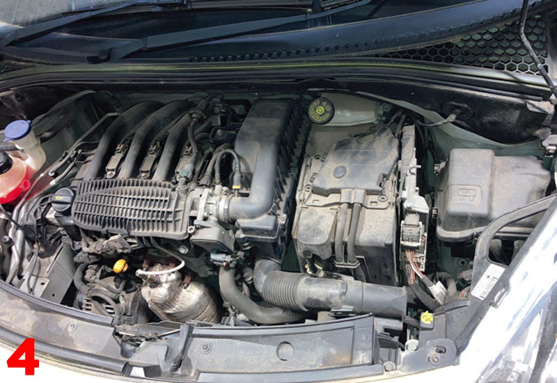
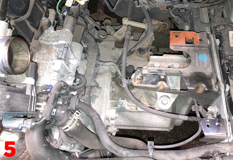
Lower the vehicle lift to gain access to the engine bay (Fig.4), remove the engine ECU that is attached to the battery carrier, remove the complete air filter assembly, the battery and then the battery carrier, which then gives good access to the top of the gearbox (Fig.5).
Disconnect the earth cable, reverse light switch and gearchange cables, release and ease the wiring loom that is located across the top of the bell housing out of the way to give access to the upper bell housing bolts, and then remove the upper bell housing bolts.
Support the engine using either an engine support brace, sub frame mounted support or a second transmission jack, and support the gearbox with a transmission jack, then remove the upper gearbox mounting, lower the engine and gearbox assembly slightly, remove the two easily accessible bell housing bolts and ease the gearbox away from the engine. When the input shaft is clear of the clutch, lower the transmission and remove the gearbox from the vehicle.
Clutch removal and replacement
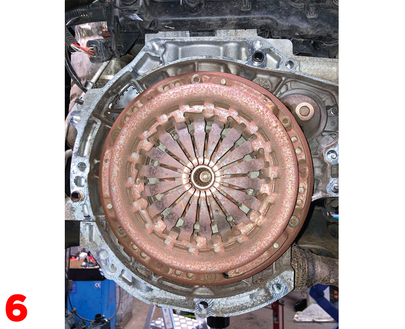
Remove the clutch assembly from the flywheel (Fig.6) by removing the six retaining bolts and ease the clutch pressure plate off the alignment dowels and remove the clutch pressure plate and clutch plate. At this point the reason for clutch slip in this particular repair was evident, as the clutch plate had worn down to the friction material rivets.
Remove excess clutch dust from the flywheel and back of the engine using some clutch and brake dust cleaner, inspect the back of the engine for any leaks that could contaminate the new clutch, rectifying if required. Remove the glaze from the flywheel surface using some emory cloth and clean again with clutch and brake dust cleaner.
Turning to the clutch release system in the gearbox, remove the release bearing and fork, check all contact points and pivot points for any wear and replace if necessary. In this repair, there was some wear on the release bearing guide tube, so this was also replaced.
Note – This clutch has a slightly different design as it is a pressed steel clutch, as opposed to a cast iron machined pressure plate, which has many advantages, whilst still meeting all the required technical specifications.
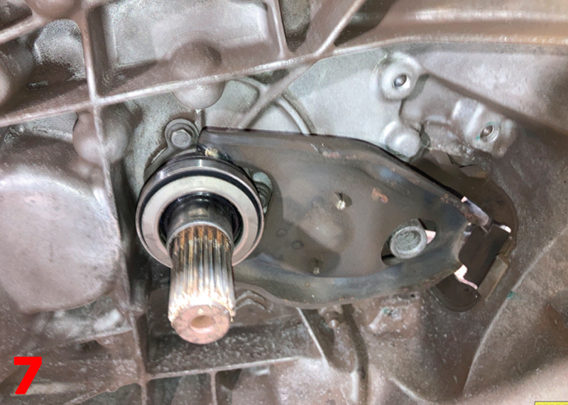
Clean the bell housing area with clutch and brake dust cleaner, apply a light smear of high melting point grease to the input shaft splines, now mount the new clutch plate onto the input shaft and move back and forth. This has two purposes: it confirms the clutch plate is correct and also evenly distributes the grease. Remove the clutch plate and wipe off any excess grease, locate the release arm and new release bearing into position and secure onto the pivot point (Fig.7).
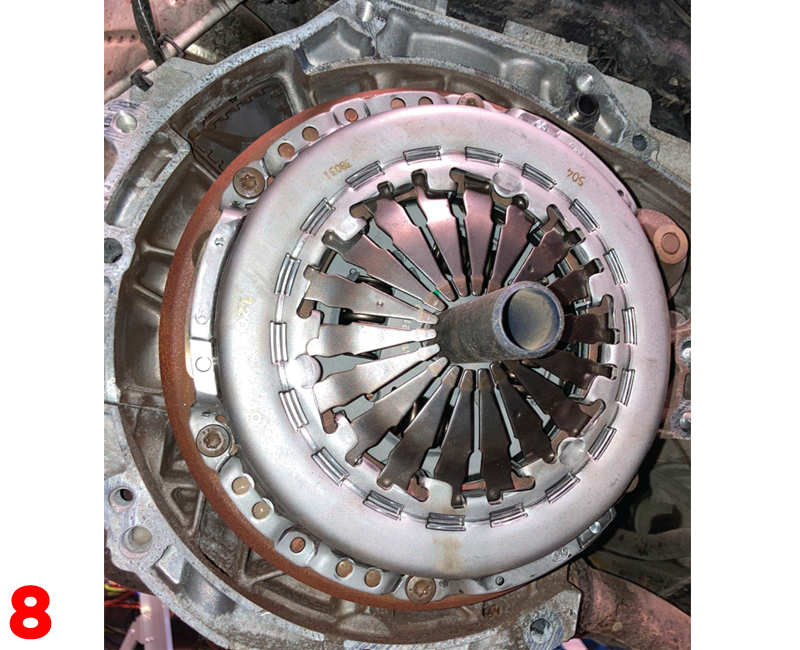
Mount the new clutch onto the flywheel using a suitable clutch alignment tool, but ensure that the clutch plate is facing the correct direction indicated by “gearbox side”. Clean the clutch pressure plate face using clutch and brake dust cleaner, align the clutch pressure plate on the flywheel dowels, insert the clutch bolts, and tighten in an even and sequential sequence, before torquing them to the manufacturer’s specification, then remove the clutch alignment tool (Fig.8).
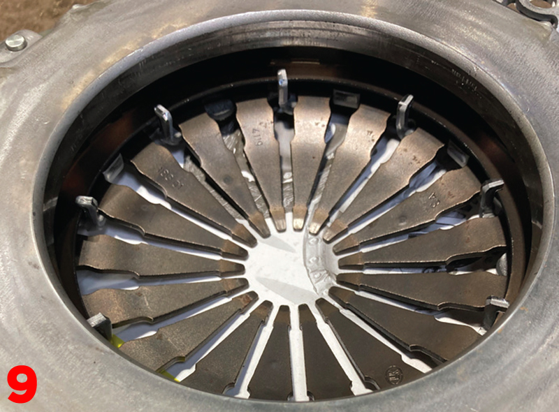
There are a couple of final checks to do before installing the gearbox: first, make sure the gearbox alignment dowels are located correctly and second, ensure the bell housing area is clear of cables etc. that could get caught when positioning the gearbox (Fig.9).
Gearbox installation
With the aid of a transmission jack, position the gearbox close to the engine, then spend a little time to ensure that the alignment is correct, and ease the gearbox into position and locate it onto the alignment dowels. Fit two easily accessible bell housing bolts and tighten, then fit the upper gearbox mounting and bolt into position. Refit all other components in reverse order of removal and replenish the gearbox oil.
After the battery lead has been reconnected, reset all electrical consumers and carry out a full road test to ensure that the repair has been successfully completed.


