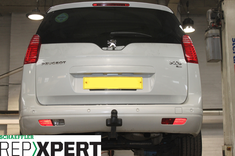
This month, REPXPERT’s Alistair Mason replaced the clutch in a Peugeot 5008 Semi- Automatic 1.6 HDI. The semi-automatic in the 2012 5008 is actually a manual gearbox with an automatic shift and clutch actuation, and whilst it is a significant job, with the right advice, technicians should be able to complete the job in four hours.
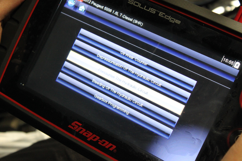
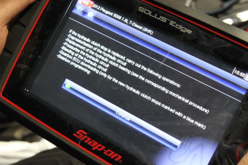
Technicians require a diagnostic kit to allow them to depressurise the hydraulics and, later, re-pressurise them. On this particular occasion, Alistair used a Snap-on Solus (see below), but whatever equipment is used, it needs the correct facility before starting the job.
Step-by-step guide
First, disconnect the battery positive lead, unbolt the harness/fuse box (see below) and remove it so the fuse box can be placed on top of the engine.
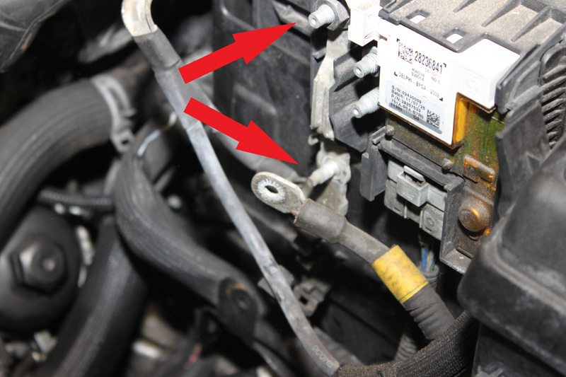
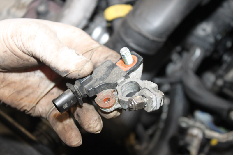
Unbolt the negative terminal and disconnect the multiplug to remove it, and then take off the battery clamp and the battery charge status unit (see below).
Disconnect the cold air intake pipe and detach the battery cover, which includes the cold air intake pipe, and then lift out the battery.
This vehicle has a plastic battery tray and a metal one, which can both be removed, but note the metal one is retained by a bolt in the wheel arch. Unbolt the gearbox mount fixings, leaving the central nut until later. Unclip the adjacent harness from its retaining bracket and remove the bracket.
Unplug the rear gearbox ECU connector, but remove the front one first, as they are interlocked, then unclip the harness and stow clear of the gearbox. Before access to the upper bell housing bolts can be gained, another harness support bracket needs to be removed. Unbolt the starter motor bolt and the upper bell housing bolts, including the removal of the guiding studs. Use the wheel locking key to slacken the wheel bolts, raise the vehicle, remove the wheels and slacken the driveshaft nuts on both sides. Take the engine undertray away and any fixings from the front bumper undertray – however, it won’t come out yet, as both front wheels and arch liners need to be removed to allow access to the bumper connections.
Unbolt the fixing, securing the bumper to the front wing, then pull it out from the wing clips on both sides. Next, disconnect any multiplugs to the bumper for fog lights, horn and parking sensors. Unbolt the RH subframe support bar, lower the vehicle, unclip and unbolt the top bumper fixings and then remove it all together. It is worth noting that the front undertray will drop to the floor when disconnecting the bumper. Drain the gearbox oil into a suitable receptacle.
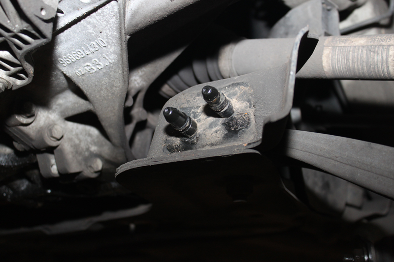
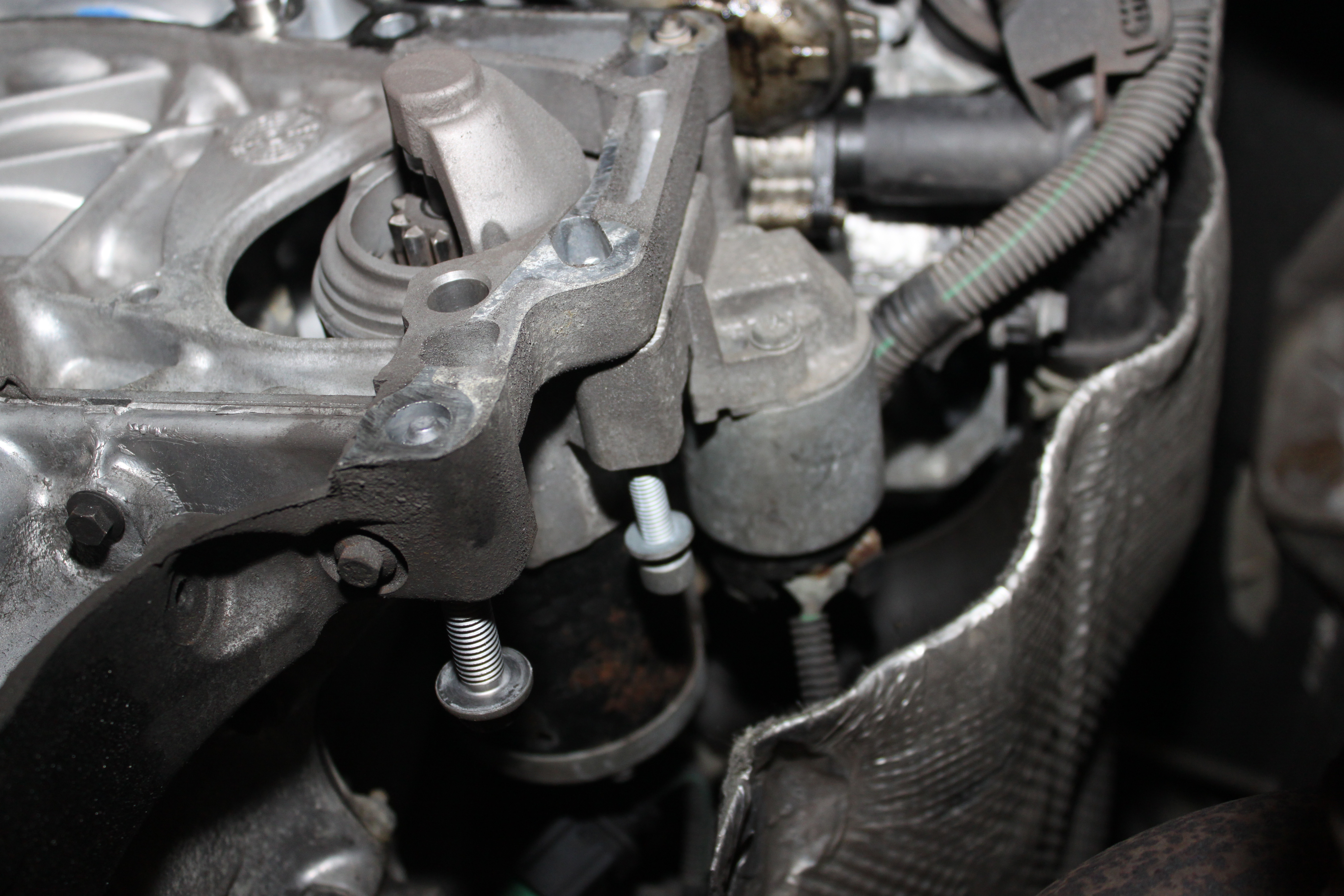
To remove the gearbox, the subframe has to be removed, so unbolt the lower ball joints and the anti-roll bar links. Next, remove the front subframe bolts, the undertray support bracket and the subframe side legs which, when unbolted, slide off two spikes (see below) on the subframe.
Release the lower ball joints and unclip brake hoses, disconnect the ABS and brake pad warning cables, then manoeuvre the suspension leg to remove the LH driveshaft.
Next, remove the exhaust clamp and rear tie bar centre bolt to allow the engine to swing, then jack the front of the engine to swing it forward. With rear access improved, unbolt the PAS pipe from the top of the subframe and remove the steering rack bolts to subframe.
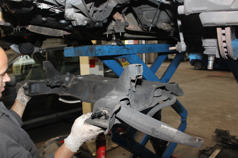
Secure the steering rack to suspend it in place, so the subframe will drop independently. Unbolt the exhaust support bracket from the subframe, then remove the rear subframe support straps and swing them out of the way. Support the subframe on a transmission jack, before undoing the remaining subframe fixings and lowering safely (see below).
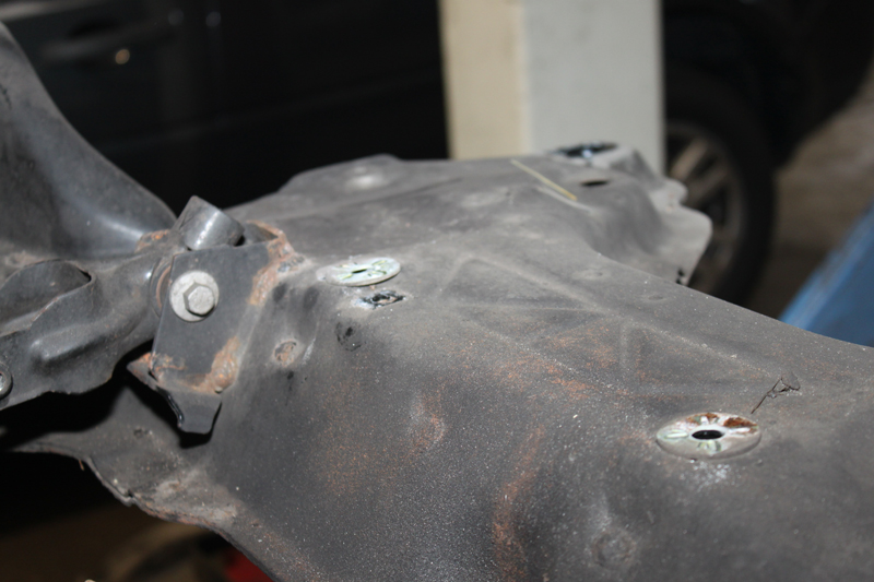
Note the two loose washers sitting on top of the subframe from underneath the steering rack (see below).
With the subframe removed, unbolt the RH driveshaft centre bearing retaining plate, and then disconnect the driveshaft completely. Unclip the rear engine heatshield and remove its support bracket, as it is concealing the remaining starter motor bolts.
After detaching them, leave the starter in position (see below).
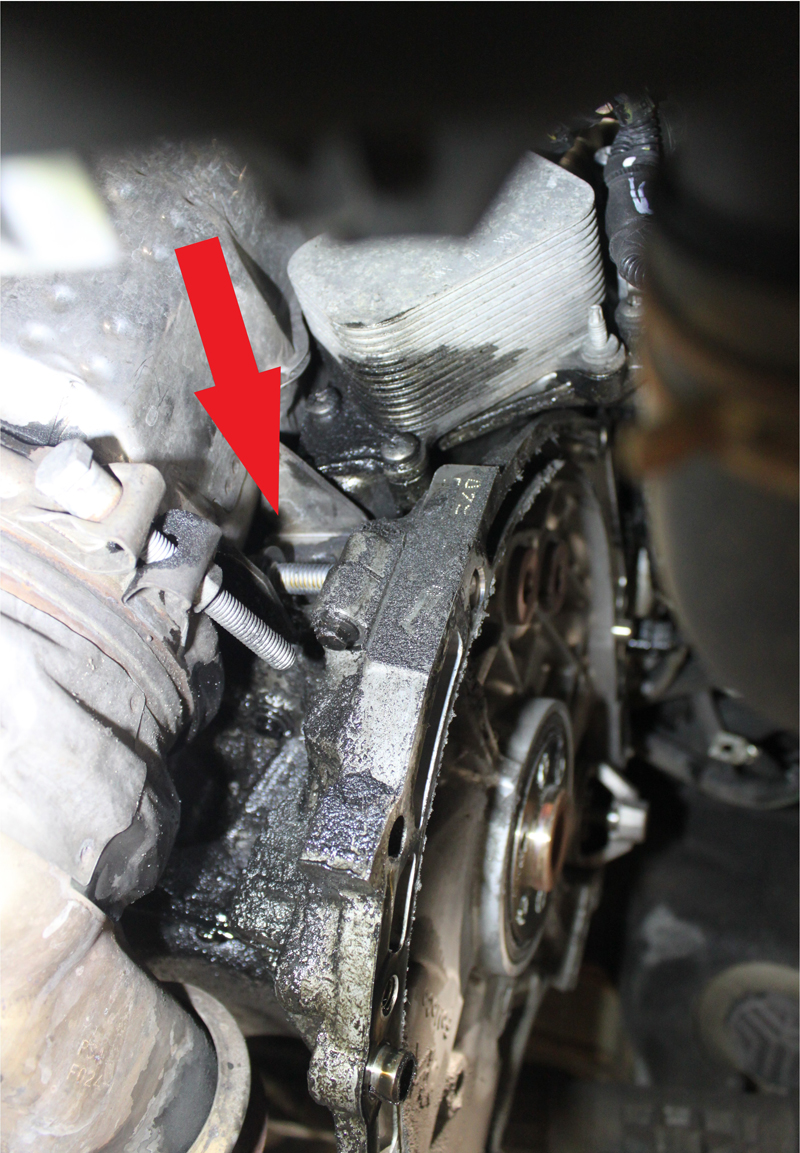
Remove the catalyst support bracket, which, again, conceals a bell housing bolt (see below) which can then be removed. Don’t forget to unbolt the earth strap from the rear of the gearbox.
After supporting the engine and gearbox, the remaining gearbox mounting nut can be removed, as well as the remaining bell housing bolts, then slowly remove the gearbox in a safe way.
With the gearbox removed, the CSC pipe can be disconnected and blanked to minimise fluid loss, and the multiplug disconnected. The bell housing should be cleaned, if necessary, and the old CSC removed and replaced, noting that it has an input shaft on the rear face that should be treated with care.
On this occasion, the old dual mass flywheel was replaced, as it had bearing damage.
After carefully refitting all the parts and refilling the gearbox with the correct spec of oil, reconnect the diagnostic tool (see below) to allow the ECU to go through the bleeding process, and operate the gear selection process to check that it all works.