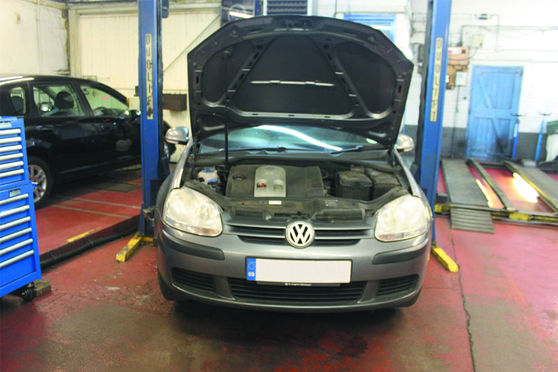
A full clutch replacement guide for a 1.6 petrol VW Golf FSI model; BLF engine code.
The Volkswagen Golf is a very popular vehicle on the UK’s roads, with many engine and model options available to choose from. In this month’s ‘clinic’ we’re going to be taking a look at the 1.6 FSI Golf with a
BLF engine code.
Recommended labour time: 3.7 hours LuK clutch kit P/N: 622333200
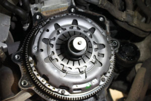
The vehicle came in with an unusual noise when the clutch pedal was depressed fully and, upon further investigation, when the gearbox was removed it was found the release fork had worn and was working against the diaphragm fingers of the clutch cover.
The release bearing was also worn. The LuK part supplied and fitted comes complete with the clutch, drive plate guide sleeve, release fork and release bearing. The workshop equipment used to complete the
repair was a two post ramp, engine support beam, transmission jack and a clutch alignment tool. If the vehicle is fitted with alloy wheels then ensure that the locking wheel tool is available before you undertake the repair.
The first thing to do is to disconnect the battery (for safety reasons). Now disconnect the air mass sensor plug and breather pipe and remove the engine cover which also houses the air filter; in this case it was quite a tight fit on the locating pegs but it will pull off with a little extra force. Remove the battery and battery housing to expose the top of the gearbox and disconnect the earth lead that is bolted to the gearbox mount.
Next we needed to disconnect the gear linkages by removing the locking washers that hold the gear links to the reverse lever and the main gear selector lever. The gear link cables are held in position on the top of the gearbox by means of a bracket (see below).
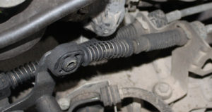
We found it easier to unbolt the bracket as a complete unit and stowed it safely into the bulk head.
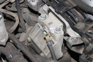
Unbolt the slave cylinder by removing the two bolts holding the bracket in place on top of the bell housing. Do not disconnect the hydraulic pipe – you’ll only need to clamp the pipe and then stow into the bulk head as a complete unit. Unbolt the earth cable from the gearbox mount (see below), disconnect the wiring loom bracket found at the front of the gearbox and disconnect the reverse light plug
(see below).
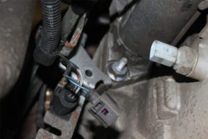
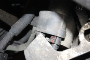
Disconnect the main starter cable and the multi-plug by pulling back the red locking tab (see below). Now unbolt the starter motor bolts and remove.
Remove the top two bell housing bolts and install the engine support beam. Now unbolt and remove the top gearbox mount bolts and mounting bracket completely to give more room when removing the gearbox. Raise the vehicle and remove both front wheels and the N/S front wheel arch liner.
Unbolt the N/S drive shaft bolt and disconnect from the wheel hub. Unbolt the driveshaft from the flange on the gearbox and remove. Next unbolt the O/S driveshaft bolts from the gearbox flange and stow the drive shaft out of the way. Remove the two bolts holding the bracket of the pendulum support
and then remove the bolt and pendulum support from its position.
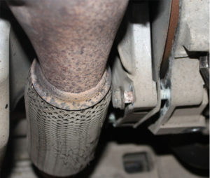
Remove the bell housing bolt from the rear, which is located just above the driveshaft flange. Support the gearbox with a transmission jack and remove the bottom bell housing bolts. There is no need to disconnect the exhaust as you’ll have just enough room to move the bolts (see Fig 5).
The remaining bolts can then be removed and the gearbox carefully lowered out of position.Remove the old clutch, bearing release fork and guide tube and then check the flywheel for signs of heat stress or excessive wear. Clean the first motion shaft splines and any debris from the bell housing. Put a small dab of high melting point grease (not a copper-based product) on the first motion shaft splines and
make sure the new driven plate slides freely back and forth. This not only spreads the grease evenly but also makes sure you have the correct kit. Wipe away any excess grease from the shaft and driven plate hub.
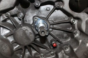
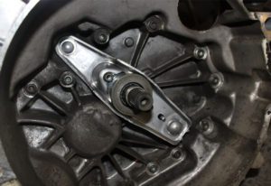
Using a universal alignment tool and checking the driven plate is the correct way round (note “Getriebe Seite” is German for “Gearbox Side”), the clutch can be bolted to the flywheel evenly and sequentially (see below).
Make sure the dowels haven’t become dislodged or damaged and replace any that have. Install the gearbox and make sure the bolts are secured and all mountings are refitted before removing the supporting transmission jacks. Refitting the rest of the components is the reverse of removal.


