
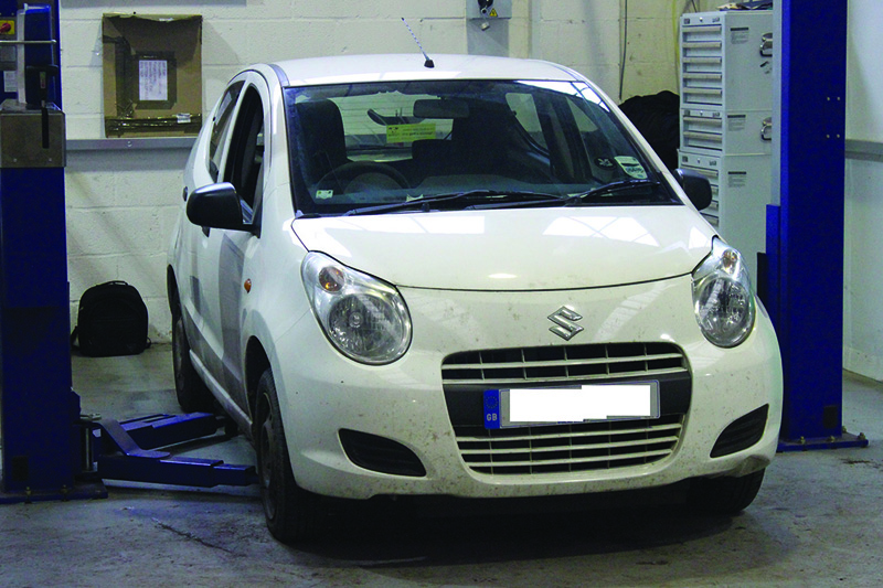
This month’s article documents a clutch replacement in a 2010 Suzuki Alto, fitted with a 1.0L, three-cylinder K10B engine, which has covered more than 70,000 miles. The customer reported clutch slip, which was confirmed by a short road test, and clutch replacement was advised.
The Suzuki Alto is quite a popular car on today’s roads – its initial cost being relatively low and with a good return on fuel. Suzuki launched the Alto in 1979 and it has been on the UK roads since 1981. The latest Suzuki Alto is the eighth generation.
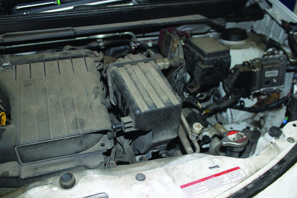
When opening the bonnet and carrying out an initial inspection, working space is at a premium, but with a little guidance, this is a good repair for any garage with a book time of 5.1 hours.
For this fix we used the following workshop equipment: a two-post ramp and a transmission jack. With the car placed on the ramp, starting in the engine bay, disconnect and remove the battery, battery case and battery carrier. The wiring loom retaining clips need to be unclipped from the battery carrier when removing.
Now remove the air box/induction noise damper (see below) allowing more access to the gearbox and bell housing area. Slacken the clutch cable and then remove the cable from the clutch release arm, open the plastic retaining clip to release the cable and then slide the outer cable away from the support bracket (light lubrication may help the rubber slide out of the bracket) and stow in the bulkhead area. Remove the clutch cable support bracket as this gives a little extra room.
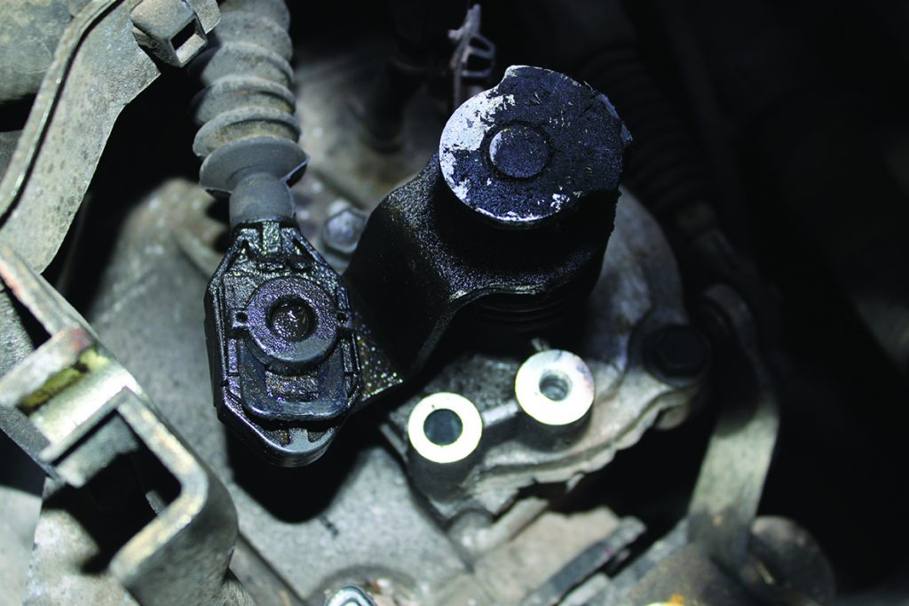
Disconnect the reverse light switch multiplug and stow the loom in the inner wing. Disconnect the gear change cables from the selector mechanism by removing the ‘U clip’ from the front cable (see below) and then detaching from the ball pivot. Disconnect the rear cable by removing the bolts from the pivot point bracket and removing the assembly (note – there is a small nylon bush located in this assembly that can fall out). Slide the outer cables upwards and out of their support bracket and stow in the bulkhead area, then disconnect the gearbox earth wire and bracket.
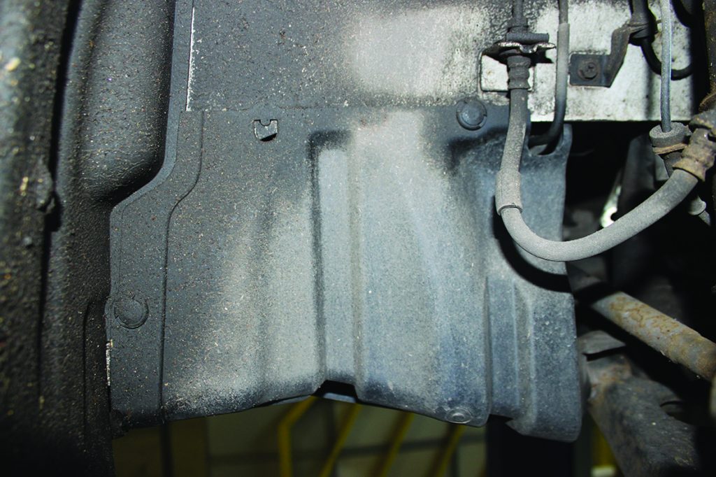
Now remove the upper bell housing bolts whilst the vehicle is on the ground and the bolts are easily accessible, storing in order and location. Next, slacken both driveshaft hub nuts and raise the vehicle to waist height. Remove both front wheels and hub nuts and the plastic shield in the N/S/F wheel arch area (see below), raise the vehicle to access the underside, drain the gearbox oil and then remove the locking pins from both bottom ball joint nuts and then take out the nuts and release both bottom ball joints. Both driveshafts can then be released from the respective hubs.
Then, using a lever, ‘snap’ the inner driveshaft joints out of the gearbox, as these are retained by spring-loaded retaining rings, and remove the driveshafts and stow safely. Now take out the rear gearbox mount which is done by releasing the mounting from the bracket, and then the bracket from the gearbox – it is worth mentioning that the mounting and the bracket cannot be fully removed, but moved to give enough room to work.
Remove the rear bell housing bolts, which are now accessible, and support the engine (we used a transmission jack in this instance) close to the bell housing area. Next, remove both the front gearbox mounting and the mounting bracket from the gearbox, lower the transmission jack about 50mm to aid gearbox removal and remove the final bell housing bolts. The gearbox can now be taken from the vehicle, either by lifting it out by hand or using a second transmission jack.
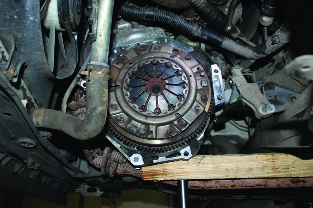
With the gearbox gone (see below), the clutch can be removed from the flywheel and, as suspected, the clutch had been worn out. This vehicle is fitted with a solid flywheel, so inspect for any damage or heat cracks, confirm the flywheel is serviceable and remove the glaze from the flywheel face with some Emory cloth and clean the flywheel area with some clutch and brake dust cleaner. Finally, remove the release bearing from the release arm in the bell housing.
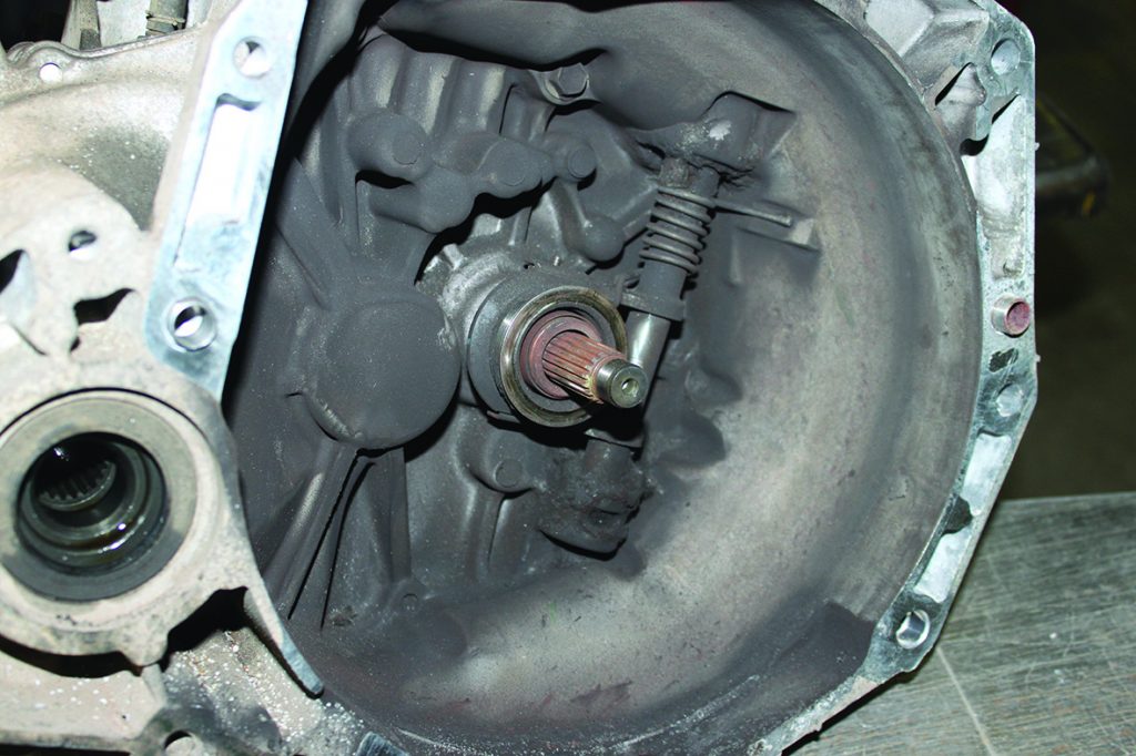
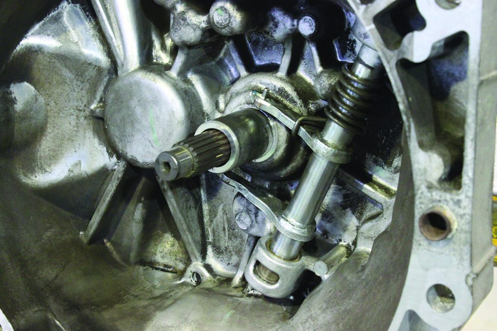
At this point we noticed that the release fork/arm had restricted movement due to the build-up of clutch dust at the pivot points and would not return to its rest position (see below), so we cleaned out the area with clutch and brake dust cleaner, and inspected the release system for any wear and carried out a check for correct and full operation (see below).
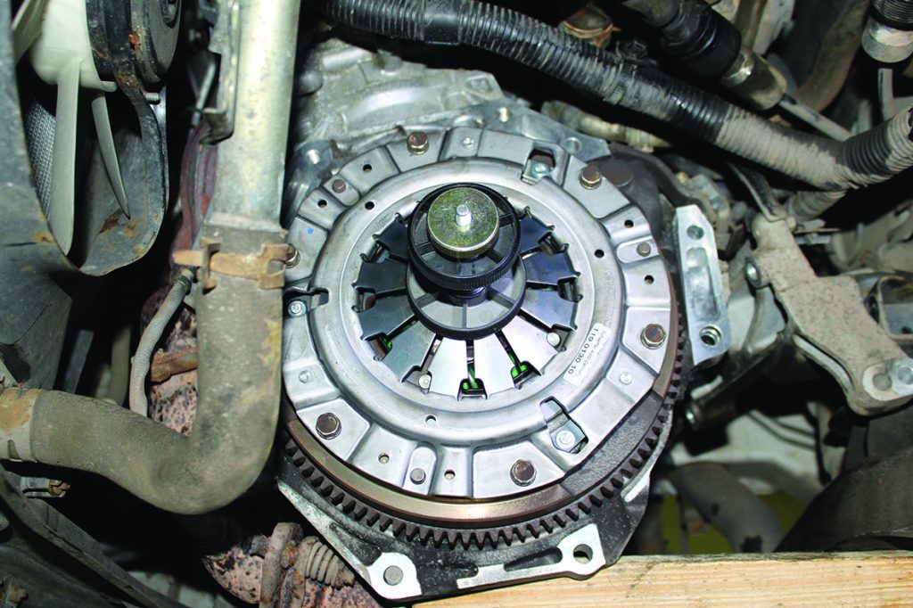
Fit the new release bearing, applying a very small amount of high melting point grease to the pivot areas as these are all metal. Apply a small amount of high melting point grease to the gearbox input shaft splines, then mount the clutch plate, confirming its correct position, and remove the clutch plate, wiping off any excess grease. Now mount the new clutch assembly onto the flywheel (see below) using a clutch alignment tool, ensuring the clutch plate is installed correctly so that the ‘Gearbox side’, or ‘Getriebe Seite’, markings on the clutch plate are facing the gearbox, tightening and torqueing the bolts evenly and sequentially.
Re-fit the gearbox in reverse order of removal and refill the gearbox with oil. Before fitting the clutch cable, check the cable for free operation and when adjusting always remember to leave a little free play at the top of the pedal to ensure a full release. Once the repair is complete, carry out a road test to ensure the clutch and gear change operation is correct and that all electrical items have been reset after re-connecting the battery.


