This month, REPXPERT’s Alistair Mason replaced the clutch in a Fiat 500 Abarth – the sporty offspring of the Fiat 500.
With the manufacturer recommending that the engine be removed first, Alistair decided that course was traumatic – and, more pressingly, impossible! – so he followed a more conventional approach, even though the booking time was longer than the original five-and-a-half hours allotted. Below is a commentary of how he achieved this.
Step-by-step guide
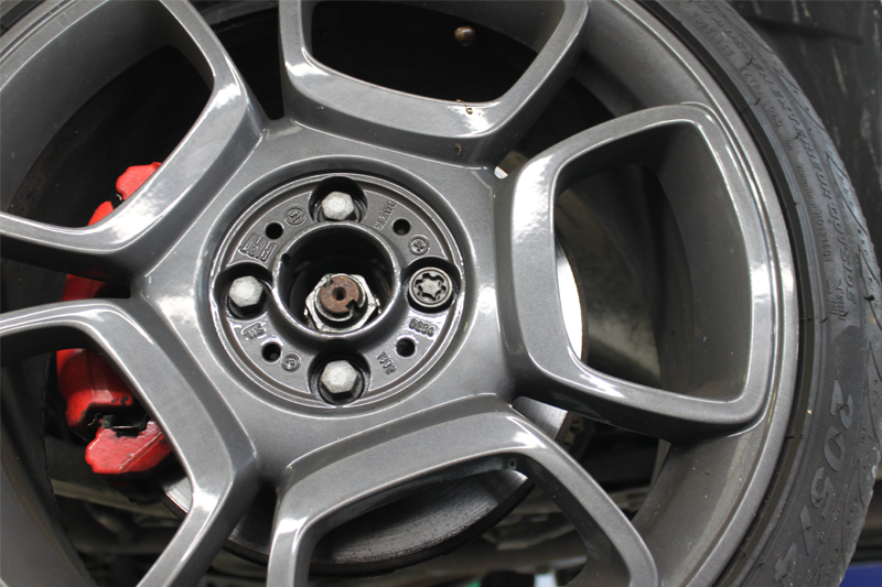
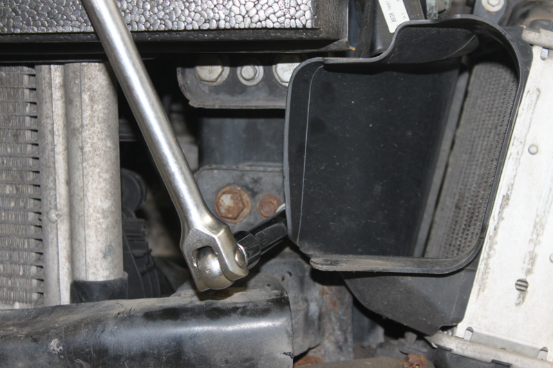
Firstly, with the car on the ramp, Alistair used extra blocks of wood to access the jacking points, so he didn’t damage the Abarth’s body kit on the ramp legs. He noticed that the standard socket needed to be modified to remove the driveshaft nuts, as there was a generous radius in the cavity preventing a standard socket getting on the nut (see below). As a result, Alistair decided to leave the wheels on and swing the complete chassis leg, with driveshafts attached, to release the CV joints from the gearbox.
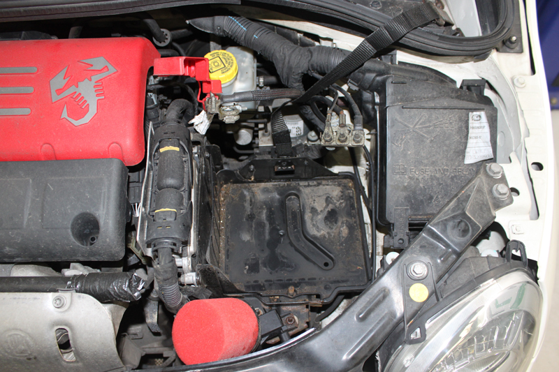
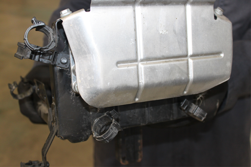
After further investigations, it was obvious that the battery and tray needed to be removed to gain access to the gearbox mount and upper bell housing bolts. He then disconnected the battery terminals and strap, then lifted the battery out of the car. With the Fiat being such a small car, most things under the bonnet were attached to the battery tray (see below) by a myriad of clips and needed to be detached.
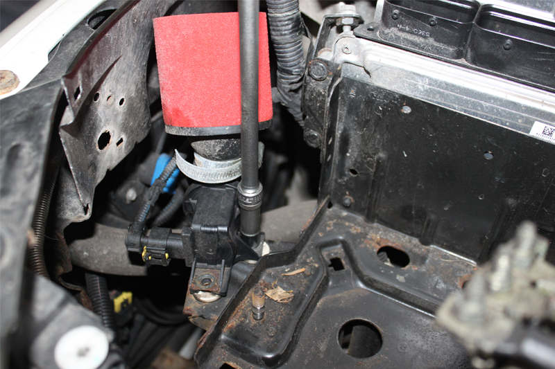
The next step was to disconnect the diverter valve with its flashy red filter (see below), then remove the two ECU plugs.
Expectedly, a number of cable and hose retaining clips later, and not forgetting the three fixings, the battery tray could be lifted free (see below).
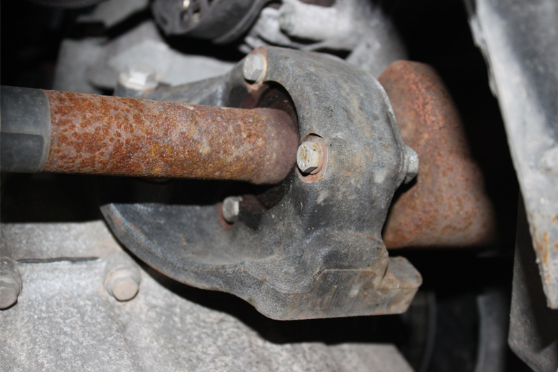
Needing a break from ‘clip designers’ heaven’, Alistair then ventured underneath the car and released the bottom ball joints, retaining the driveshaft support bearing in its housing (see below).
The gearbox was entombed above the subframe, but, because the LH subframe side leg was removed, it was teased out. This was achieved by uninstalling the LH wheel arch liner and the front bumper cover, both retaining their nuts and screws, as well as disconnecting the spotlights and indicators.
With the bumper cover removed, Alistair could see the LH subframe leg retaining bolts, shared with the bumper armature (see below), so these were removed as well. At the rear of that leg were two additional fixings, which, once again, had to be removed.
The exhaust pipe support bracket was impeding some of the bell housing bolts, so that needed to be detached, and at this point it became clear that the whole subframe should be lowered, except the RH leg, so after disconnecting the oxygen lead multiplug and unclipping the lead, the subframe bolts were loosened.
Alistair left the steering rack and anti-roll bar in place, so he removed the bolts, retaining them to the subframe. After uninstalling the engine tie bar mounting bracket bolt and strapping up the steering rack, the subframe bolts were unscrewed and it was carefully lowered.
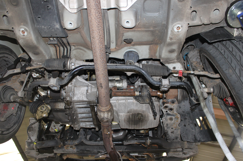
With the job opening up (see below), Alistair had to go back up top to release yet more clips, starting with the water temp sensor plug and all the other multi plugs, until the harness could be stowed safely out of the way of the bell housing bolts. The intercooler pipe was retained by a bracket and nut that needed detaching, and then the clutch concentric slave cylinder could be disconnected and the pipe stowed safely after removing it from another clip or two.
After removing the upper bell housing and starter motor bolts, it was time to support the engine and gearbox. Two transmission jacks were deployed, one for each, then the driveshaft CV joints were removed from the gearbox. Alistair had a split boot on the LH joint, so it came apart when pulled.
The gearbox was supported by a mount on the LH side, with three bolts conveniently screwed into the end of the gearbox in the wheel arch, so these were removed. The lower bell housing bolts were also detached, leaving the gearbox and engine to be split and the gearbox to be safely lowered to the ground.
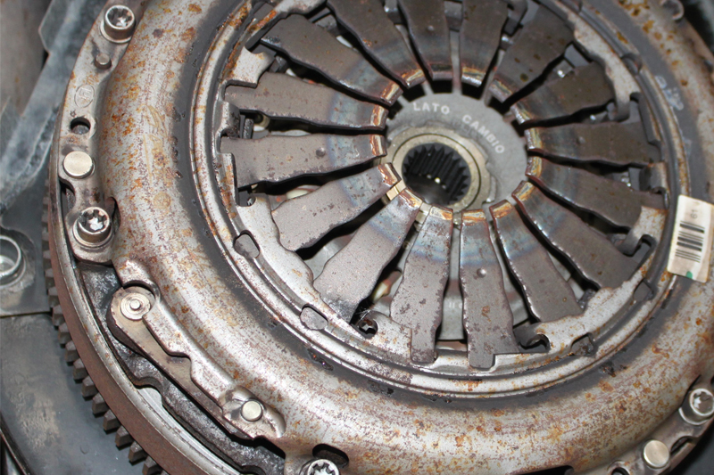
Before removing the old clutch, Alistair, as with every clutch replacement, observed the direction the clutch plate was fitted (see below) – ‘LATO CAMBIO’ is Italian for ‘gearbox side’. He sat the cover and plate together in the correct orientation until the new parts were fitted in a similar fashion.
After cleaning the bell housing and carefully replacing the CSC, the new clutch was then fitted with a clutch alignment tool to the dual mass flywheel. After ensuring the gearbox dowels were in place, the gearbox was then replaced and the rest of the car reassembled.


