
Regular contributor Josh Jones ponders this question after carrying out a particularly interesting vehicle diagnosis.
With cars changing as fast as they are at the moment, I ask myself this question pretty much every day. With the onslaught of new propulsion technology coming into the market, it seems like EVs will dominate the market sooner than I first considered.
Ever since my apprentice days, I have always wanted to know as much as possible about cars and the way they work. At first, this was just fascination, but pretty soon, I realised that knowledge paid my bills and as soon as I had my own place, I realised that earning money is just as important as enjoying what you do! I understood that in order to be in demand by a good employer, I needed to have something that the guy paying my wages doesn’t have, and that one thing is subject knowledge. This has always been my number one priority at work and so far it’s served me pretty well. So, with the powertrain revolution well under way, what do I need to do to ensure that I’m as good a tech in 20 years as I am now? A fault I investigated the other day made me feel slightly less worried…
It was a crank, but non-start scenario. The diesel engine had cut out on the driver very near the end of their journey – less than a mile in fact. The driver was able to restart the engine for brief periods of time following the initial cut out and limped it back to base. By the time the vehicle came to me, it would not start at all, but it would still crank.
A DTC read of the engine control showed P0A0F was stored: ‘engine failed to start’. As this was the only DTC stored, I knew that the control unit fault monitors had not detected any immediate short/open circuits or specific component malfunctions. I assumed the strategy to log the fault code would simply be an extended cranking time with no increase in engine speed or commencement of fuelling. With this being a compression ignition engine, I accessed the fuel pressure reading via live data and found that there was no rail pressure build during cranking, and I couldn’t hear any lift pump activity (there was one fitted). My scan tool has the functionality to test run the lift pump so I ran that test next. No pump activation.
After establishing that I was on the right track to diagnosis, I followed my diagrams to rule out the possibility of a relay or fuse fault, and confirmed ECU activation of the pump as far as the applicable junction box. Everything looked normal so I referred back to the diagram. It showed that the in-tank pump was not directly powered from the junction box, but via a control/driver unit at the rear of the vehicle. The pump utilised three-phase power, with the separate control unit/inverter providing the necessary conversion from direct current to alternating current, in order to provide more adjustable power and control over the flow of fuel to the rail. The output of the inverter was adjusted via a PWM signal from the engine controller (Fig 1).
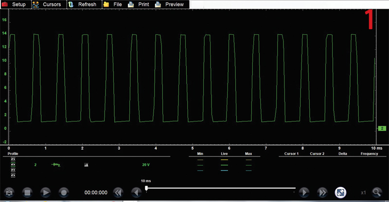
When probed (at the corresponding pin at the inverter unit) in the non-start scenario, a good PWM was present immediately after key on, and continued throughout the long cranking period (at a slightly different duty cycle). This showed that the engine ECU was definitely asking the pump to provide flow.
Probing the power and ground pins to the inverter module confirmed a good ground path and that the power I had confirmed at the junction box upfront was present where required. It was looking more and more like pump failure, but the really interesting bit was next: checking the inverter output to the pump.
Since the start of my career, I have worked on vehicles using direct current systems. That is, until the last few years. Recently, I have had to invest a lot of time into understanding three-phase conversion and operation. I have done this partly by attending training courses, and partly through my own personal study. By approaching it in this way, I have found that you need a combination of both types of training to end up proficient in this area.
The three-phase output pins were also available at the inverter unit, so I first confirmed that the system did not utilise high voltage and the wires weren’t orange! I only own a two-channel scope, so I decided to view each phase one by one. It was a very interesting trace to view, and it was at this point I realised I was learning about how an EV is powered without actually working on an EV.
Tracing the pump output control phase wires (Fig 2) clearly shows you how incredibly rapid and precise the switching of transistors can be in order to effectively synthesise the characteristics of a rotating generator output. As each individual phase happens, you can see initial start-up bursts of voltage to accelerate the pump, which is then followed by the individual ramping pulses that average out to form a sine wave. Subsequently, the pulse peaks then becomes smaller again towards the end of the phase.
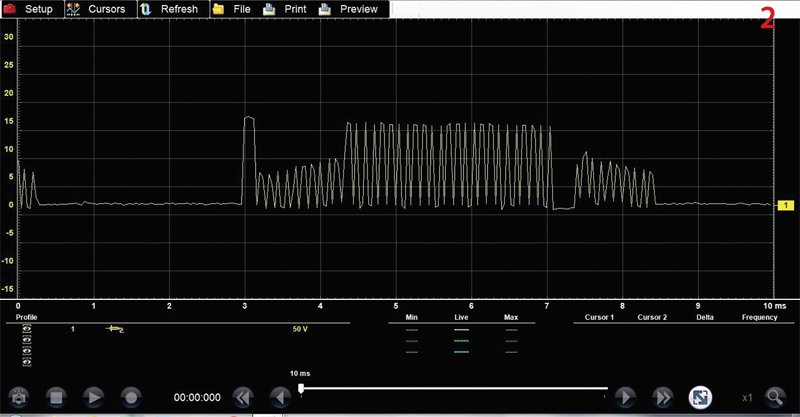
Effectively, I was viewing a similar trace to the one I would expect to see if I were looking at a traction motor inverter output. In the future, I hope I end up doing just that if I am to keep working on cars as propulsion gradually swaps to high-voltage power.
I talk to a lot of people in this trade about where they see it going and I generally hear the same thing: there won’t be much to do when cars are all electric. I completely disagree. For me, I don’t view the future of the aftermarket as a cliff edge, where one day I am comfortable thinking I know all there is to know about diagnosing faults on cars with conventional powertrains, and then the next I am totally out of my depth. Rather, I try to match my learning pace with the pace of the introduction of new technology.
If I understand the operation of a three-phase pump, this means my transition toward working on vehicles fitted with multiple AC systems in the future will be smoother and infinitely less scary.


