REPXPERT’s Alistair Mason replaced the clutch on a semi-automatic Peugeot 107, which was fitted with a 1L 1KR engine. The vehicle had covered just over 50,000 miles and reportedly suffered from clutch ‘slipping’.
Equipment used: two-post ramp, engine support and transmission jack, diagnostic machine, locking wheel bolt key and radio code.
The customer complained that the clutch slipped when driving the vehicle and that it was slow to pull away. A short road test later confirmed that the clutch needed to be replaced, with an official repair time of nearly four hours. Because these ‘city’ cars can be subjected to a lot of stop/start driving, the service life of the clutch can be significantly reduced. This provides independent repairers with an excellent opportunity to carry out a clutch replacement.
However, the challenge of replacing the clutch in a semi-automatic vehicle may be daunting, so Alistair has produced a step-by- step guide to illustrate how surprisingly straightforward this type of repair is.
Step-by-step procedure
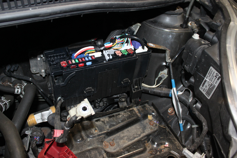
With the vehicle on the ramp, open the bonnet, remove the battery and disconnect the fuse box/ECU carrier from the battery carrier (see below).
Next, disconnect the wiring loom retaining clips and then remove the battery carrier, which, as a result, gives good access to the top of the gearbox. Now disconnect the wiring loom multiplugs from the gear change and clutch actuators, remove the wiring loom retaining brackets and stow the wiring loom to the rear of the engine bay.
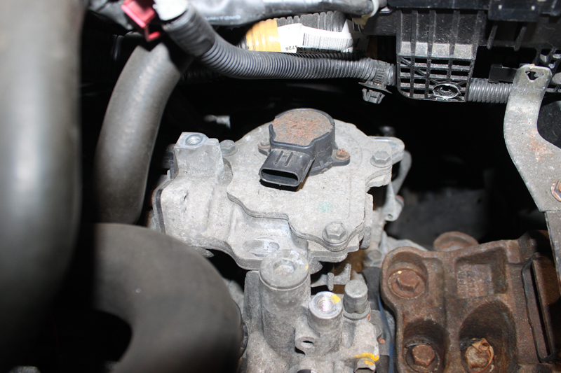
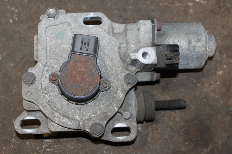
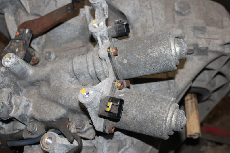
Remove the three retaining bolts from the clutch actuator unit, detach, and disconnect the two multi-plugs from the gear change actuators at the rear of the gearbox (see below).
Next, unscrew the upper bell housing bolts and the upper starter motor bolt. At this point, the ramp can be raised to waist height and both front wheels can be taken off. Once the wheels have been safely stored away, raise the ramp again to gain full access to the underside. The next task is to drain the gearbox oil. Whilst it is draining, unlock both front wishbone bolts.
Now separate both front anti-roll bar links, refit the drain plug and disconnect the N/S splash guard, allowing space for the gearbox removal.
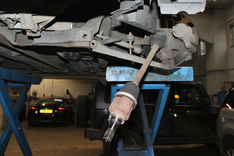
Detach the gearbox pendulum mounting from the underside of the gearbox, before disconnecting both driveshafts from the gearbox by levering them out (these are retained by ‘snap rings’ so sometimes a quick tug on the lever is required). Once removed, the hub assemblies are simple to pull out and the driveshafts are positioned to give clearance for gearbox removal (see below).
Next, remove the flywheel cover from the lower section of the bell housing, as well as the remaining bell housing bolts and lower starter motor bolt. Remember to leave one housing bolt which is easy to access, so it can support the gearbox before it is removed.
Disconnect the Lambda probe multiplug and also remove the retaining bracket, then support the engine with either a sub-frame attached engine support, an engine brace or a floor-mounted support, such as a large axle stand or transmission jack.
From the engine bay, remove the gearbox mounting on the N/S. Once removed, lower the engine slightly, support the gearbox with a transmission jack, remove the final bell housing bolt, ease the gearbox away from the engine and flywheel, and then lower the gearbox to remove.
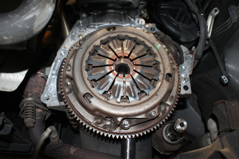
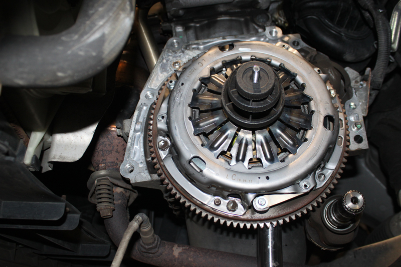
With the gearbox removed, check what clutch is currently installed. In this scenario, it was evident that a conventional diaphragm spring clutch was installed, so the usual replacement procedure applies (see below).
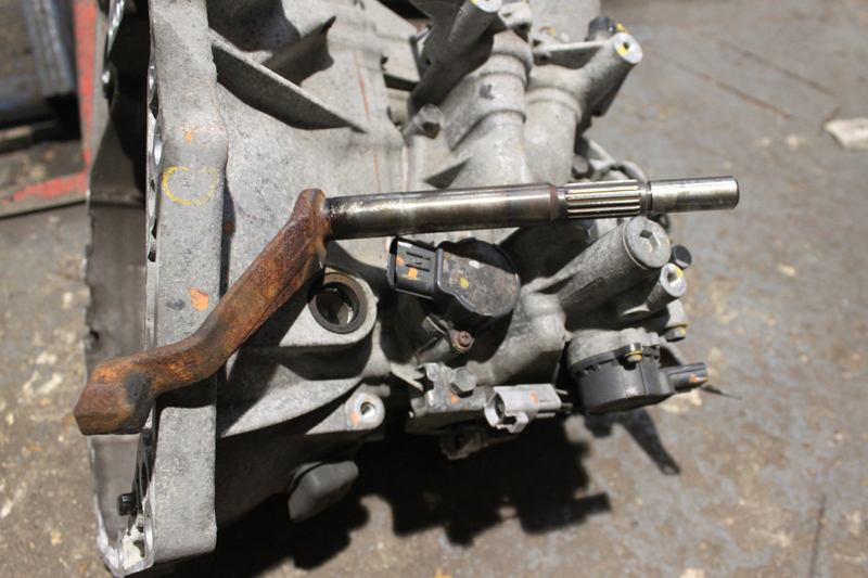
Check for any leaks from the engine or gearbox that could contaminate the new clutch, and rectify the issue if required. Now remove the clutch assembly, clean the flywheel and inspect for heat cracks. Remove the surface glaze using Emory cloth and clean the bell housing. Take off the old release bearing and actuator shaft, before inspecting for any wear on all contact areas (see below).
Before fitting the new release bearing, lubricate the moving contact points on the release system with high-melting point grease. After installation apply a light smear of high-melting point grease to the gearbox input shaft splines, and then position the new clutch plate onto the input shaft. Ensure it is correctly fitted and wipe off any excess grease.
Finally, install the new clutch using a clutch plate aligning tool (see below), confirming that the clutch plate is facing the correct direction and remembering to always tighten the bolts evenly and sequentially.
Install the gearbox and refit in reverse order of removal, refill the gearbox with the correct quantity and specification of oil, and torque all bolts to the manufacturer’s recommendation. When the repair is complete, the final task is to reset the clutch actuator using a diagnostic computer. Once reset, conduct a short road test to ensure the operation was a success.


