Following on from last month’s case study, we catch up with Pico technician Steve Smith as he begins day two of diagnosing a BMW i3 that is refusing to switch to ‘Ready Mode’ and is displaying a drivetrain error message.
Day two of diagnosis
As most workshops know only too well, having dead cars on ramps is not good for profitability and so on arrival the BMW i3 had been dragged off the ramp to a workshop bay (the relevance of which will become apparent later).
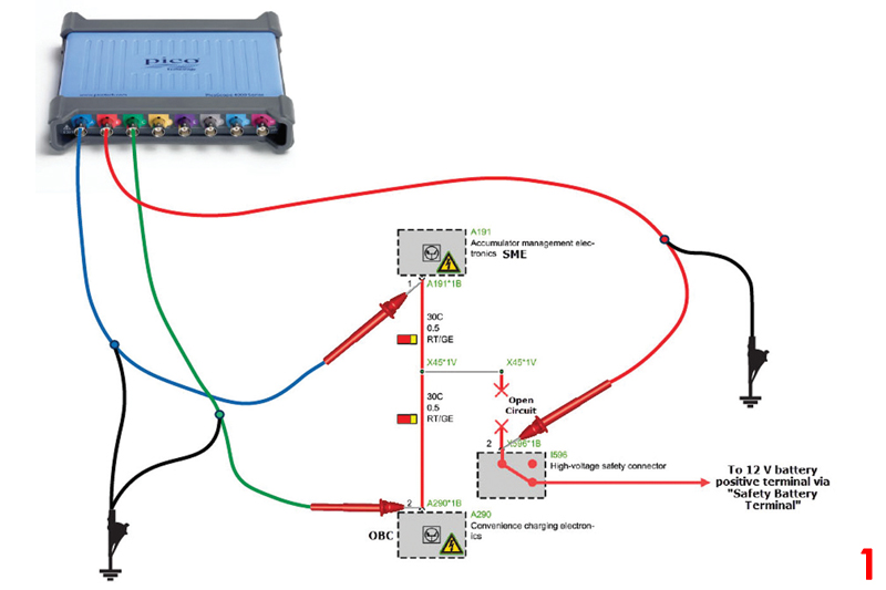
Re-measuring the Terminal 30 C voltage at the SME, OBC and high-voltage safety connector revealed the fault had moved from intermittent, and while under load, to permanent! This was great news as permanent faults lend themselves for speedier diagnosis (see the scope connection diagram, Fig 1/main image).
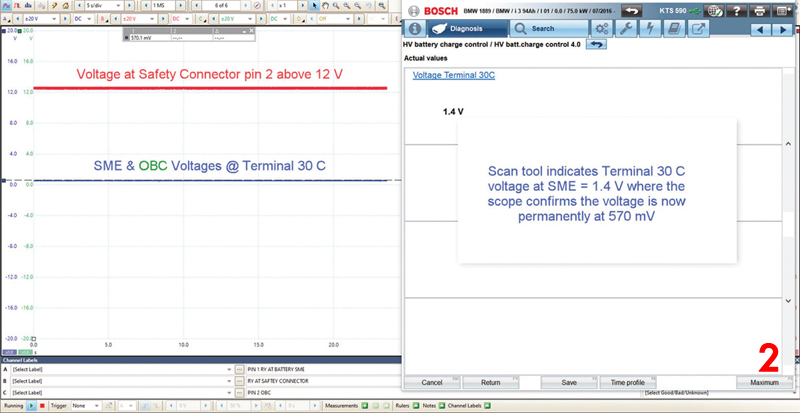
The scope confirmed that the Terminal 30 C voltage at SME and OBC was 570mV, whereas the scan tool suggested 1.4V at the SME (Fig 2). This confirmed that both the high-voltage safety connector and the pyrotechnic device (at the 12V battery positive post) are intact because we have 12V exiting the high-voltage safety connector. The 570mV that were present at the SME and OBC was most likely to be residual voltage from within these components via their respective ignition supplies (we made measurements with ignition on).
When we introduced a fused jump wire from the 12V battery positive post to SME pin 1, the result was a successful power up of the vehicle to ‘Ready Mode’ with forward/reverse drive established.
The conclusion, therefore, was that we had an open circuit (30 C) between the high-voltage safety connector and the SME/OBC. The question now was where the open circuit is located, as the high-voltage safety connector was at the front of the vehicle and the SME was at the rear.
Before I move on, let’s assume we don’t have an open circuit (even though we do), but a high resistance instead. I want to discuss and qualify the voltage drop in circuit 30 C (the high-voltage safety connector to SME pin 1), which in theory should be equal to Channel B minus Channel A. Or should it?
Because we were using the 4823 scope (which utilises common ground inputs) to measure the voltage drop, we created the math channel B-A (Fig 3). However, if we had a scope with floating inputs (4×25 or 4x25A), we could have obtained the voltage drop using only a single channel.
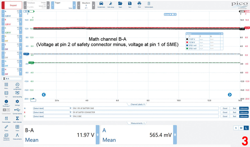
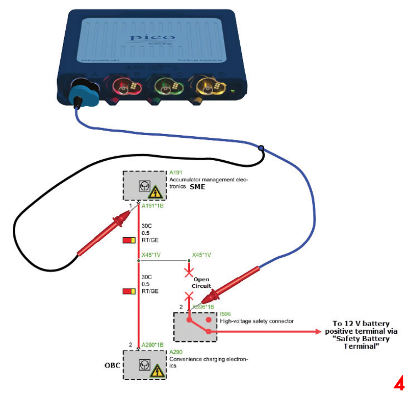
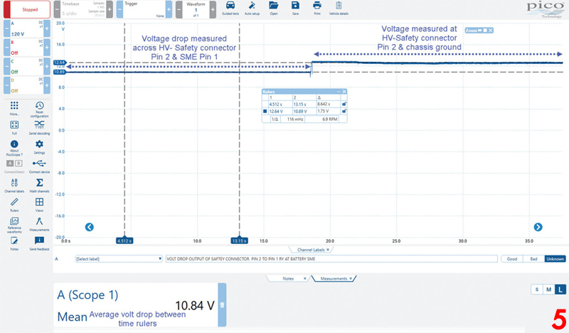
Fig 4 demonstrates the connection required to measure voltage drop in circuit 30 C (the high-voltage safety connector to SME pin 1) via Channel A on a 4425A scope.
The results in Fig 5 returned a volt drop of 10.84V, unlike the math channel of the 4823 at 11.97V.
How can we have such different voltage drop values using PicoScopes with different architectures (common and floating ground)? The answer is that both scopes are correct, the difference comes down to Ohm’s law.
Voltage drop can only be present where there is current flow (V = I x R) and with an open circuit cable there is no flowing current (had there been a high resistance instead, these values would have been near equal).
While the additional voltage drop tests above were not truly relevant to the diagnosis (we had enough evidence with the capture from the 4823 scope), the information contained within provided further evidence that circuit 30 C was ‘open’ and delivered an explanation as to why these measurement techniques returned different values.
Finding the open circuit
Tracing an open circuit within a wiring harness can be challenging at best and a nightmare at worst. Non-intrusive measurement techniques are always the best approach, as they minimise disturbance to vehicle components and hopefully reduce labour time. Because the wiring harness was routed along the outer chassis, we drove the vehicle on the ramp to improve the accessibility.
The PicoScope 6 Automotive software in conjunction with masks and alarms provided the perfect hands-free tool to capture and warn us of ‘make and break’ connections while we wiggle tested the wiring harness.
The mask feature in PicoScope can be likened to a waveform ‘trap’, where the user specifies an area of the graph where they are notified (with an alarm) if the waveform encroaches or touches the mask.
In Fig 6, I created a mask around Channel A at SME pin 1, which allowed approximately 2.8V deviation from 0V (-1V + 1.8V) before the waveform/signal touched the mask and PicoScope sounded the alarm.
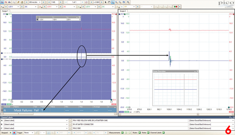
The plan was to wiggle test the wiring harness from the front to the rear of the vehicle in an attempt to momentarily ‘fix’ the break in circuit 30 C. If we were successful, the voltage should increase from 0V at the SME to 12V and the mask would capture the event and set off the alarm.
Unfortunately, no amount of harness wiggling resulted in a mask failure. However, the mask failure occurred while we were raising the vehicle on the ramp. My initial thoughts were that flexing of the vehicle had resulted in a momentary connection of circuit 30 C.
Looking at the zoomed section on the right-hand side of the screenshot, we had captured a disturbance in the electromagnetic field (EMF) emitted by the contactors of the ramp when raising the vehicle This event was also captured by Channel B at the high-voltage safety connector but with reduced amplitude. This was further proof that circuit 30 C was open and behaving like an antenna. It received the disturbance of the EMF from the ramp contactors, because the cable was not terminated but open to atmosphere.
Where to now?
When non-intrusive techniques failed us, we had to go old-school and perform continuity testing of the wiring harness. But where should we start? Looking at the wiring diagram, X45*1 was a sealed joint located at the rear on the left-hand side of the chassis and it served as a possible failure point. When we cut into the harness at this location, we confirmed the sealed joint to be in perfect condition, so we needed to make further incisions.
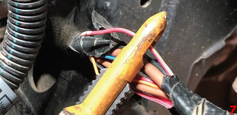
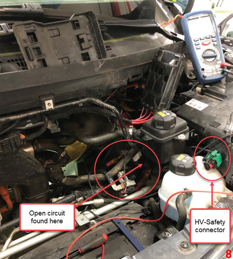
After five strategic cuts into the wiring harness, we located the open circuit approximately 50cm away from the high-voltage safety connector, directly beneath the 12V battery carrier (Fig 7 and 8).
Results and confirmation of repair
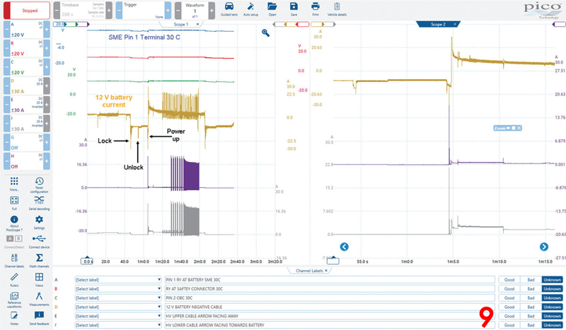
With the wiring harness repaired, fault codes erased, and trims refitted, we could charge the vehicle via an EVSE point and drive it as expected. Fig 9 shows the power-up stage to ‘Ready Mode’ after locking and unlocking the vehicle. Channel D captured the current flow to and from the 12V battery; Channels E and F captured the same events from the HV battery.
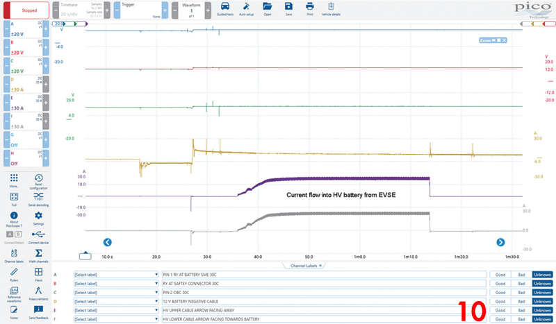
In Fig 10, we captured the current flow into the HV battery during charging via a Type 2, 7kW EVSE.
Additional comments
It never seizes to amaze me how faults occur and how they also change in nature with intrusion. The customer confirmed in the interview that there had been no previous issues with the vehicle “one day this vehicle was fine, the next day it would not power up!” How does a wire go open circuit overnight?
Once the crash circuit (30 C) had been triggered the vehicle could not power up to Ready mode until a stable 12 V had been re-established. This brings me onto the different fault conditions of 30 C during day one and two of the diagnosis.
On day one, the Terminal 30 C voltage failed ‘intermittently and while under load’. However, on day two, there was no voltage present because the vehicle had been dragged off the ramp and relocated to a workshop bay. My theory here is the movement and flexing of the vehicle/harness resulted in a total failure of the ‘weak’ crash wire beneath the 12V battery carrier.
Regarding the location of the broken wire, during the mask test, note how the amplitudes differ between Channels A and C (SME and OBC) and Channel B at the high-voltage safety connector. Could this be a clue to the location of the fault as the SME open wire (30 C ) was as long as the vehicle itself, hence lending itself to improved reception of EMF by comparison to the 50cm length of open wire from the high-voltage safety connector?
When reading through the case study and thinking about the time spent to diagnose the vehicle (20 hours including research), I started to think about how such labour content is charged and who should pay for it. Without any manufacturer warranty, the cost falls to the customer and 20 hours at £100 per (as an example) is £2,000 for labour (Parts Darts is even more expensive).
Aftermarket extended warranties will not pay for diagnosis, the repairing garage most certainly should not pay (only benefit), which leaves the tab with the customer.
Having been fortunate enough to travel with Pico and learn how other countries manage such diagnostic situations, vehicle insurance policies often include diagnostic support. Vehicles, such as those above, where diagnosis has the potential to ‘run out of control’ are commandeered by the insurance company that will then hand the challenge onto a ‘centre of excellence’ or write the vehicle off as beyond economic repair.
I am not sure if such polices are in place here in the UK, but if nothing else, its food for thought and worthy of discussion.
Many thanks to Steve and Jane Winn at Steve Winn Autocare Ltd and to Pete Melville of HEVRA for their support and shoulder to cry on during this case.


