The technical team at Continental has gone to great lengths to provide a succinct, step-by-step guide to installing a CT1092WP1 timing belt kit on a 1.6L Ford Focus II.
Vehicle information: Ford Focus II (DA), 1.6L TDCI, MY 2005 with engine code HHDA
Labour time: 1.7 hours
Tools required: 2 x crankshaft centering tools OE (303-732), Tool Box V04/18; crankshaft locking pin OE (303-734), Tool Box V04/17; camshaft centering tool OE (303-735), Tool Box V04/19 – all can be found in Tool Box V04
When approaching this procedure, it is always worth noting the manufacturer’s recommendations. In this particular case, the manufacturer suggests changing the timing belt for vehicles up to 12/2005 every 240,000km/10 years.
Alongside this, Continental stresses that the multi V-belt must be changed at the same time as the timing belt. The manufacturer recommends changing the multi V-belt on vehicles up to 12/2005 every 240,000km/10 years.
Preparatory work
Identify the vehicle using the engine code. Then, disconnect the vehicle battery. Do not turn the crankshaft and camshaft once the timing belt has been removed. Turn the engine in the normal direction of rotation (clockwise) unless otherwise specified.
Next, turn the engine but only at the crankshaft sprocket, not at other sprockets. Only carry out checks and adjustments when the engine is cold, and avoid contact between the belt and harmful substances, such as engine oil, fuel or coolant.
It’s important that you comply with all the tightening torques specified by the vehicle manufacturer.
Removal
- Remove the ancillary drive belt, drain the coolant at the expansion reservoir hose, and cover the alternator in advance
- Support the engine securely using a jack and pad
- After unscrewing the four nuts, remove the front engine mount (nuts must be changed at 80Nm for the top and 90Nm for the bottom)
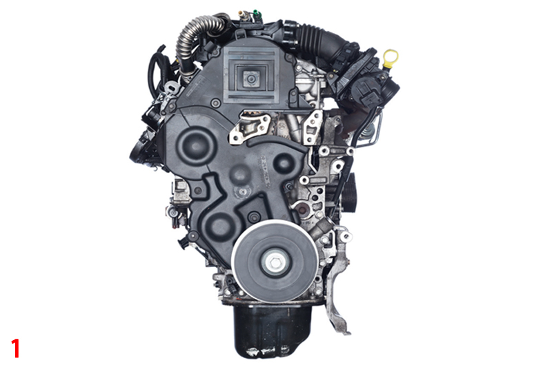
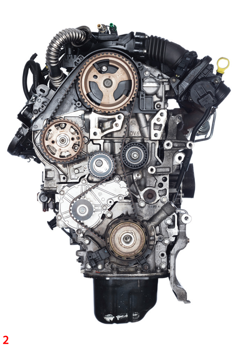
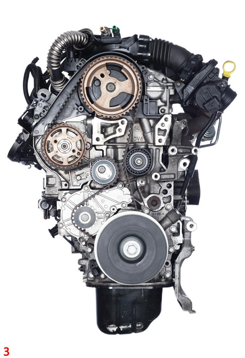
- Remove the upper guard, then unscrew the four horizontal bolts of the engine mount flange (55Nm), loosen the CS vibration damper using the impact wrench and remove, then finally remove the lower guard and re-fit the vibration damper (Figs 1 (main image), 2 & 3).
Removal – camshaft belt
- Set the valve timings to the TDC mark of cylinder 1
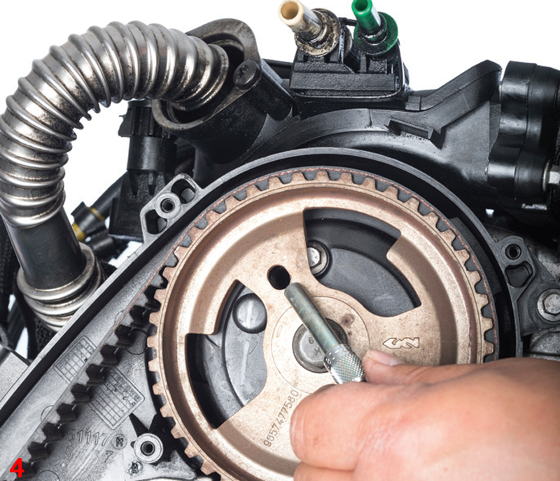
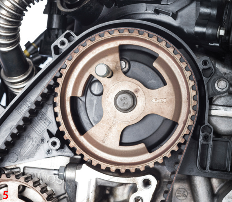
- Ensure that the camshaft sprocket bore (at approx. 10 o’clock position) is aligned with the bore in the cylinder head (Fig 4) so that the locking tool OE (303-735), Tool Box V04/19 can be inserted into the bore (Fig 5)
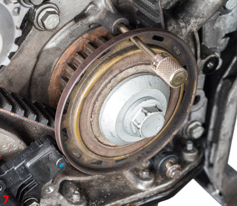
- Check the position of the crankshaft. To do so, turn the bore of the crankshaft timing belt sprocket/sensor sprocket to the 12 o’clock position, until it is aligned with the bore behind it. Insert the crankshaft centering tool OE (303-732), Tool Box V04/18 into the bore of the crankshaft timing belt sprocket/sensor sprocket and the engine block bore (Figs 6 & 7)

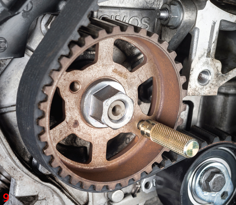
- Lock the timing belt sprocket of the high-pressure pump at the approximately five o’clock position with the crankshaft centering tool OE (303-732), Tool Box V04/18 (Figs 8 & 9)

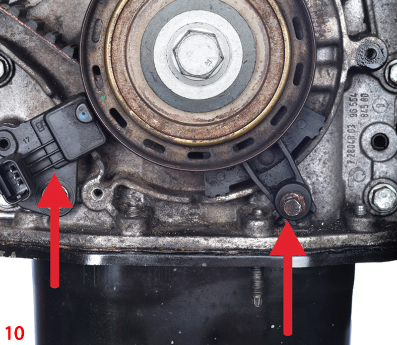
- Remove the timing belt guide on the crankshaft timing belt sprocket/sensor sprocket (approx. five o’clock position) and sensor (approx. seven o’clock position) (Fig 10)
- Loosen the tensioning pulley nut and release the tension on the timing belt
- Now remove the timing belt
Installation – camshaft belt
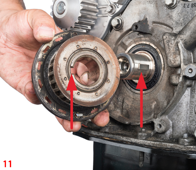
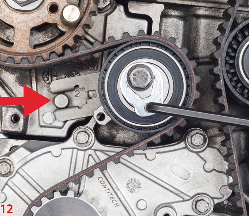
- Beware of the crankshaft timing belt sprocket/sensor sprocket sliding off the crankshaft when removing the timing belt! Before fitting the new timing belt, check that the pulley spring for the crankshaft timing belt sprocket/sensor sprocket is correctly positioned (Fig 11). Fit the components contained in the kit. Check the remaining sprockets, such as the camshaft sprocket and crankshaft sprocket, for damage. When fitting the tensioning pulley, ensure that the tensioning pulley fork is installed centrally above the cam (Fig 12)
- Fit the timing belt in the direction of crankshaft rotation. Take care to ensure that the timing belt is not kinked during the fitting! The timing belt must be tight between the sprockets on the tight side
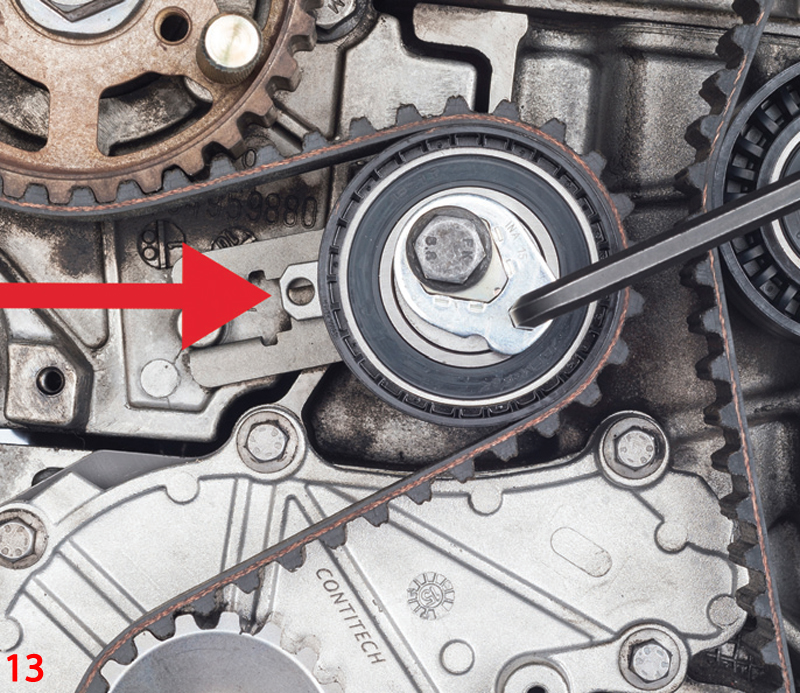
- Tension the timing belt via the tensioning pulley. To do so, turn the tensioning pulley eccentric counterclockwise using the hex key and tension until the marks align (Figs 12 & 13). Tighten the tensioning pulley nut (23Nm)
- Remove the locking and centering tools
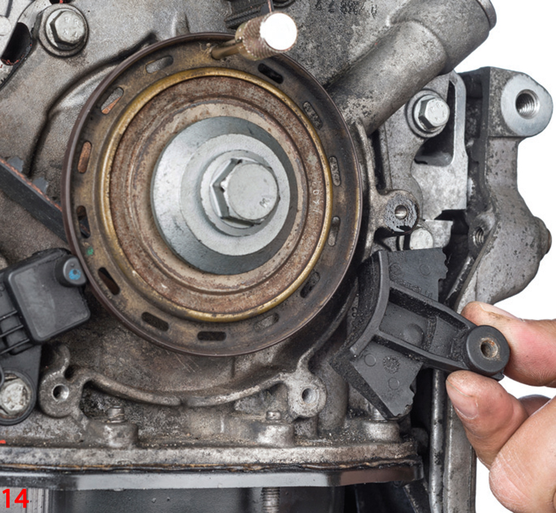
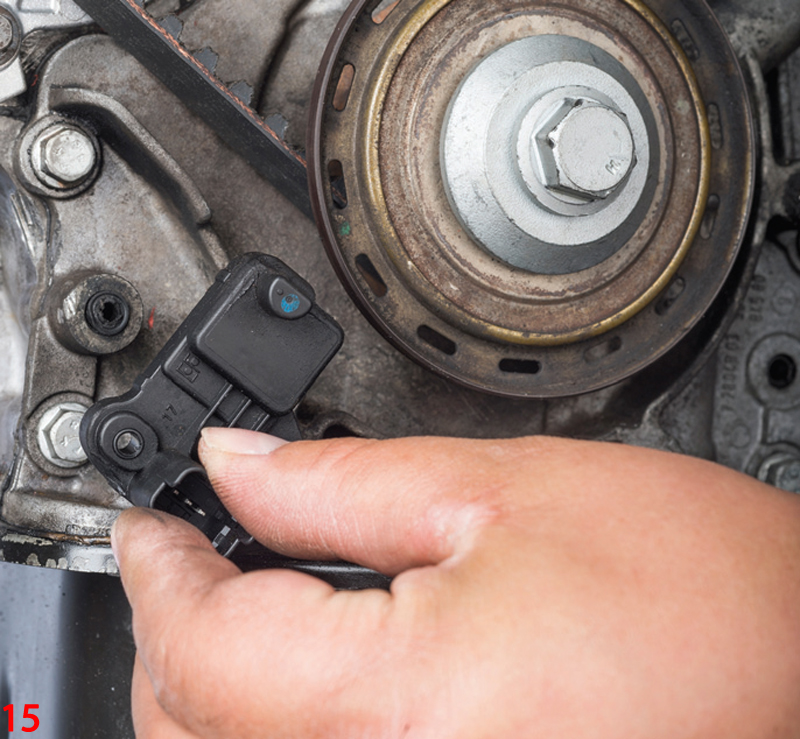
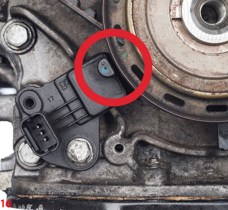
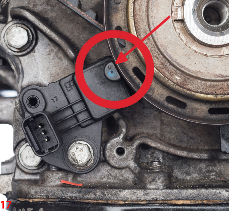
- Re-install the timing belt guide on the crankshaft timing belt sprocket/sensor sprocket (approx. five o’clock position) and the sensor (approx. seven o’clock position) (Figs 14 & 15). Ensure, as you do this, that the sensor does not touch the sensor ring (Figs 16 & 17)
- Turn the engine through 10 revolutions at the crankshaft in direction of the engine rotation
- Set the valve timings to the TDC mark of cylinder 1 – setting the same as the removal above. It must be possible to insert the locking and centering tools again. Ensure the tensioning pulley marks (Fig 13) are aligned. If they are not aligned, repeat the setting process, then remove all locking and centering tools again
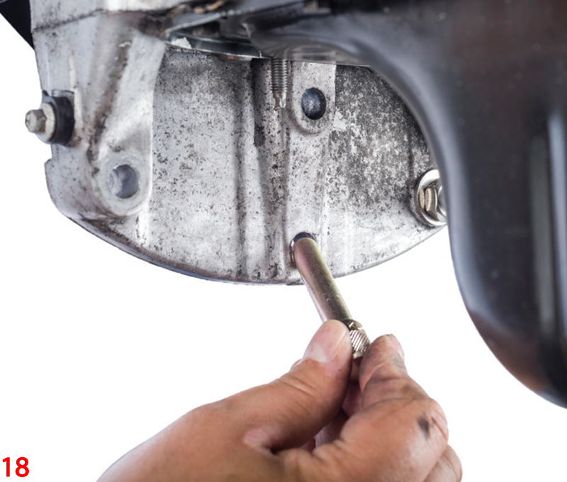
- Assembly should then be carried out in the reverse order to the removal. Fit the new crankshaft bolt and tighten it in two stages. First: 30Nm; then, second: 180°. To do so, lock the flywheel using the crankshaft locking pin OE (303-734), Tool Box V04/17, and then turn the crankshaft until the locking tool is aligned with one of the slots in the flywheel (Fig 18). Then remove the locking tool again
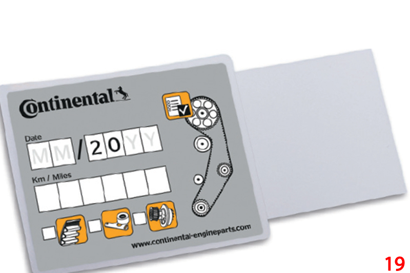
- Record the changing of the original Continental timing belt on the sticker supplied and stick this in the engine compartment (Fig 19)
- Finally, carry out a test run or test drive


