
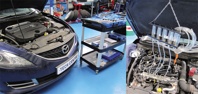
As the diesel engine becomes more efficient, and therefore more popular, with most manufacturers offering them right across their ranges, maintenance and understanding of these systems is obviously becoming more and more important in the automotive industry.
Laser Tools offer a number of diesel technology-based tools and the tool we are focusing on in this article is suitable for common rail diesel engines. Pressure loss on a common rail fuel system can often result in poor or no engine starting, rough running and poor acceleration.
A common reason for pressure loss is excessive fuel being returned to the fuel tank (also referred to as ‘back leakage’). If the injector(s) suffer from excessive back leakage, the fuel pump cannot generate enough pressure to let the system operate correctly. This can be more obvious at start and tickover as fuel pressure (at these low engine speeds) is directly related to engine
revolutions.
A blocked or malfunctioning injector will send more fuel back to the tank, while a worn injector may be injecting too much fuel into the combustion chamber, and thus sending less fuel back to the tank. The 5260 kit makes both conditions obvious. It is comprehensive and (usefully) can cater for up to 10 injectors in one test. 40 adaptors are included for Bosch, Siemens, Denso and Delphi CRD systems.
USING THE TOOL IN 9 EASY STEPS
It’s important to have the engine warmed up, as a coldstart condition can give inaccurate results.
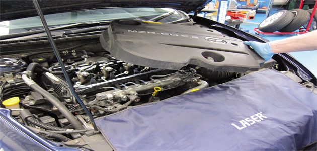
STEP 1: Modern engines are usually fitted with a sounddeadening cover over the top of the engine. Remove this to gain access to the injectors. Then check for obvious faults like leaking fuel pipes, loose or chafed vacuum pipes, or wiring, etc.
STEP 2: The fuel return pipe connectors are secured with wire or metal clips. Remove these and store in a safe place.
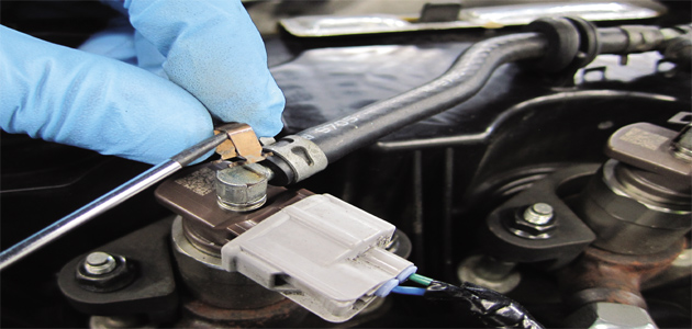
PLEASE NOTE: Adaptors are included for Bosch, Siemens, Denso and Delphi CRD systems.
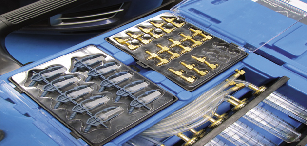
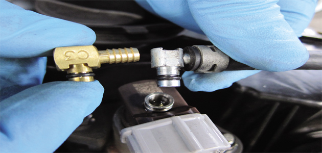
STEP 3: Select the correct adaptor and compare to the vehicle’s return line connector. Fit the adaptors to the flexible tubes from the 5260 chamber block.
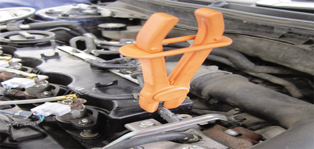
STEP 4: On some engines, the fuel return lines share a connection with the fuel pump and fuel can be forced back out from the return lines when the engine is started. So either seal off the ends of the fuel return pipes, or clamp off the main return pipe as illustrated, using Laser Tools’ 4386 hose clamp.
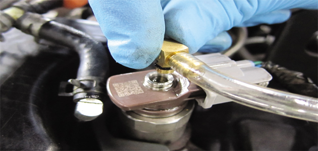
STEP 5: Fit the adaptor and tube to the injectors, keeping them in order. They are a simple push-fit, there is no need to use securing clips.
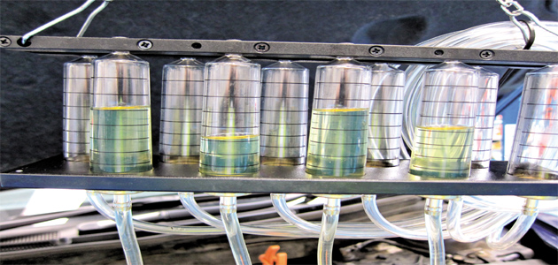
STEP 6: Hang the chamber block from a convenient point under the bonnet. Keep the tubes tidy, making sure they’re not near any pulleys or belts. Start the engine and leave to idle for a few minutes.
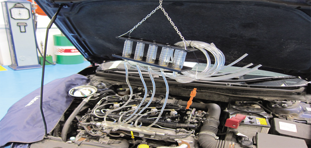
STEP 7: The chambers will start to fill with fuel. Stop the engine when they are 50-75% full. Chambers showing a difference of approximately plus or minus 10% from the others are displaying a fault condition. In this case the no.2 cylinder injector is obviously injecting more fuel into the combustion chamber than the other three.
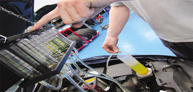
STEP 8: Any injector which has a back leakage problem will have a higher fuel level in the chamber. When the test is complete, drain the chambers into a suitable container. Place a finger over the chamber vent to avoid spillage as the tube is placed over the container. Lift finger from vent and the fuel will drain into the container.
TO FINISH: Remove the clamp from the return fuel line and refit the return fuel line connectors to the injectors, remembering to fit the securing clips. Before the engine cover is refitted, run the engine for a minute or so and check all lines and pipes for fuel leaks.


