The Honda CR-V was launched in 1995 and is a popular multi-purpose vehicle. Now onto its fourth generation, this handy guide should prove to be a worthwhile read for any garage in the UK aftermarket faced with clutch replacement on the third generation 2.2 CDTi model.
No special tools are required to complete the repair, but you need to support the engine, gearbox and subframe. We used four transmission jacks, but you could use two jacks and some rope to support the subframe. A two-post ramp was used for the replacement.
Open the bonnet and, for safety reasons, disconnect the battery terminals. Remove the battery and the housing tray. Slacken and remove the air filter case fixing that is attached to the battery support bracket, and remove the air flow pipe that is in two sections. The air filter case is removed by carefully levering the rear of the case from the two push fit connector bracket; the bracket will also need to be removed (Fig 1 below).
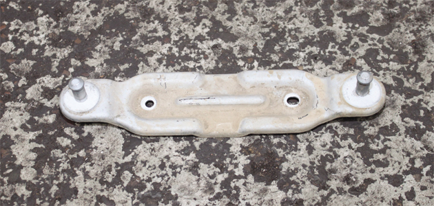
Fig 1
Remove the battery support bracket and stow the terminals safely to the side. The reverse light connector is now exposed and can be disconnected and stowed safely. Remove the gear selector linkages by slackening three bolts from the bracket. It is less fiddly than unclipping them individually from the bracket and can be stowed safely as one complete unit (Fig 2 below).
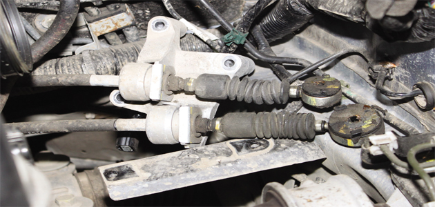
Fig 2
Three further multi-plug connectors to be disconnected are located on the gearbox. Remove two bolts from the slave cylinder bracket (Fig 3 below).
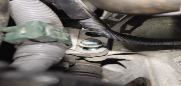
Fig 3
Remove one nut that holds the hydraulic pipe (Fig 4 below) and stow safely as one unit. Remove the bracket with the earth cable still attached and stow safely.
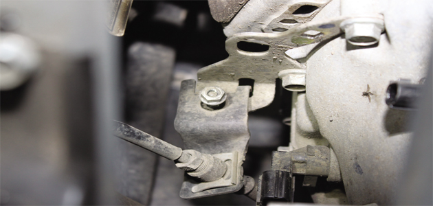
Fig 4
Remove both wheels
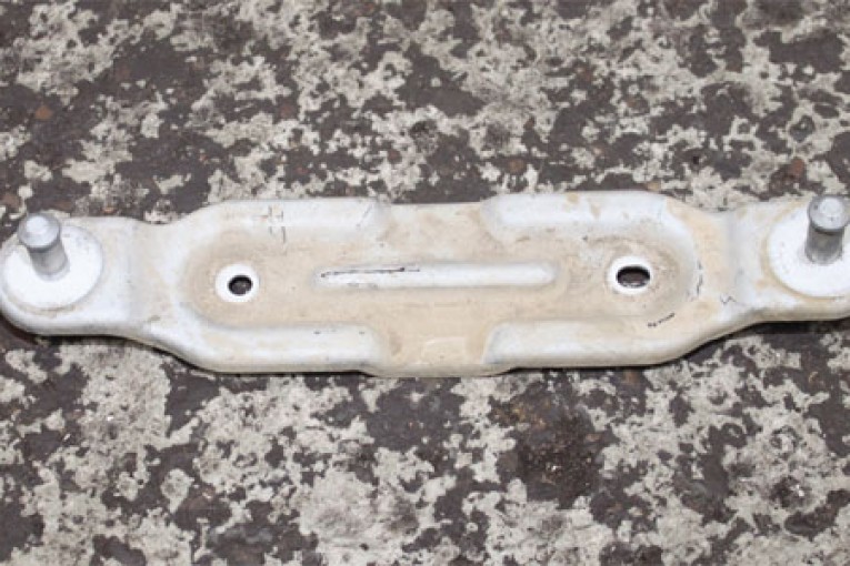
Remove the two nuts and one bolt that hold the top engine mount in place. The mount does not need to be removed. Slacken the two bolts from the gearbox mount and remove. Before raising the vehicle, remove two bell housing bolts from the top of the gearbox. The bolt closest to the bumper is in a slightly tricky position and holds in place a wiring harness (Fig 5 below).
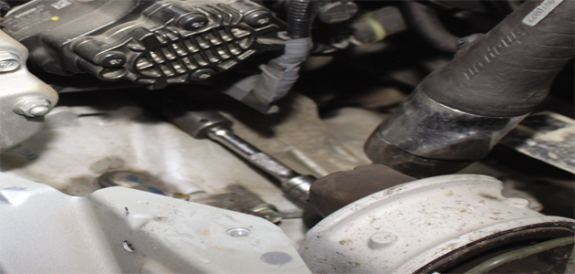
Fig 5
Remove both front wheels and raise the vehicle. Remove the push-in retainer clips holding the under shield flaps inside the wheel arch – there are two clips on each side. Remove all retaining push-in clips holding the under shield in place – there are quite a few and you will find two that are hidden, one on each side towards the front that also need to be removed (Fig 6 below).
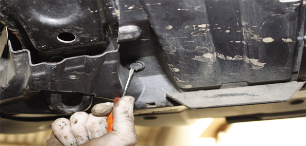
Fig 6
Pull away the complete under shield, taking extra care of the flaps from inside the wheel arch, as it is all one piece. Support the engine and gearbox with transmission jacks and drain the gearbox oil.
Remove two nuts and one bolt on each side, securing the lower suspension arm to the ball joint and unlink. Remove the rubber bracket from the exhaust closest to the catalytic convertor. Unlink the front-end prop shaft by slackening the four double hex bolts. Remove the bolt that secures the power steering pipe bracket to the subframe (Fig 7 below) and unclip the pipe from the two clips holding it in place.
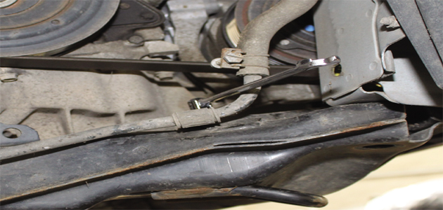
Fig 7
Free the driveshaft on the left-hand side and remove. Slacken the eight subframe bolts (four on each side) to allow the subframe to lower slightly without removing it fully. Remove the bolt that secures the engine stabiliser and lower the subframe from the rear.
Intercooler pipe removal
Remove the intercooler pipe – this blocks two bell housing bolts – and then remove the eight bolts from the bell housing. One of the bolts is in an awkward position so we used a spanner to remove this (Fig 8 below).

Fig 8
Another bolt is secured through the starter motor. With the clutch removed, check the dual mass flywheel (DMF) for signs of heat stress and evidence of grease loss.
The DMF should also be tested for free play and rock between the primary and secondary masses. LuK tool number 400 0080 10 is specifically designed for this purpose on all LuK manufactured DMFs. Full instructions and tolerance data for all LuK DMFs are contained on a CD that comes with this special tool.
Clean the first motion shaft splines and any debris from the bell housing, which is especially important when a release bearing has failed. Put a small dab of high melting point grease – not a copper-based product – on the first motion shaft splines, and make sure the new driven plate slides freely back and forth.
This not only spreads the grease evenly, but also makes sure you have the correct kit. Wipe any excess grease off the shaft and driven plate hub. Using a universal alignment tool, and checking the driven plate is the correct way round (note “Getriebe Seite” is German for “Gearbox Side”), the clutch can be bolted to the flywheel evenly and sequentially.
Before fitting the gearbox, make sure the locating dowels are in place and not damaged. Refit any that have become dislodged and refit the gearbox. Make sure the gearbox bell housing bolts are secured before lowering the jack. Refitting is the reverse of the removal.


