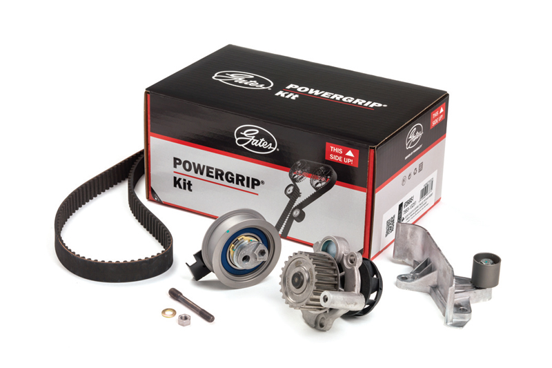
Gates explains how comebacks and common installation errors are being reduced with a focus on appropriate tools and specific fitting instructions.
In the latest series of Gates technical workshops, the Gates Technical Training and Support Team is providing mechanics around the UK with logical explanations for premature timing belt failures often considered as ‘mysterious’.
Synchronous Belt Drive Systems (SBDS) from two engines with different ‘automatic tensioners’, different belt tension setting procedures and different sets of precision tools have been catching the attention of mechanics on a regular basis.
The engines involved are:
■ Renault 2.2dCi, 2.5dCi engines –2000 onwards
■ Ford 1.8 TD, TDCi, TDDi (all eight-valves)
Technicians sometimes compromise the job by failing to allow engines to return to ambient temperatures. Another common error is to assume that automatic tensioners require no specific tension setting procedures. Without these procedures, automatic tensioners cannot perform effectively and efficiently.
Belt design and construction
Ahead of discussions about the specific installation and belt tension-setting issues, it is worthwhile providing some context by briefly discussing the design and construction of all Gates belts.
The internal ‘s’- and ‘z’-twisted tensile cords contribute not just strength, but also balance and deliver stabilising qualities to the synchronous belt. These combine to help keep the belt centralised on the pulley. Precise belt tension is the key to retaining the central position. It is this that ensures efficient overall performance of the SBDS.
Renault 2.2-2.5 tensioner and setup
Fitted to Renault Espace, Laguna, Master and Traffic models, these engines are also a fixture of some Vauxhall and Nissan ranges. In each case, precise timing belt tension is established through a two-stage process. A Camshaft Locking Tool is required (GAT 4760B) to set the precise tensioner position. With the tool in place, the position is set by means of a lever arm on the locking tool itself. When the lever arm is level with the top of the locking tool, high tension has been achieved.
Note: This is only the desired initial tensioner position.
The Camshaft Locking Tool is then removed and the engine rotated manually, through a specified number of revolutions. The Camshaft Locking Tool is now replaced and the correct installation tension is set by aligning the raised edge of the lever arm. It must be level with the top of the tool. Both stages are essential to the procedure. Completion of both stages is the only way that installation tension can be achieved.
Ford 1.8 TD, TDCi, TDDi (all eight-valves)
Frequently installed on models such as the Ford Galaxy from 2009 and the Ford Mondeo from 2012, advice from the Gates Technical Training and Support Team is that at commencement, the engine must be atambient temperature. Locking and setting tools from the Gates Professional Tools Range (GAT 4830 and GAT 4304) are also recommended for the job.
Vital steps in the fitting procedure include locking the crankshaft and flywheel, locking the camshaft (rear of the engine) and loosening the camshaft sprocket while holding it in place so it’s free to rotate on the taper. This is important because otherwise the top span of the belt cannot be tensioned.
Other important steps include:
■ Rotating tensioner anticlockwise
■ Lining up indicator with the centre of the slot
■ Bolt torque = 50Nm
■ Rotating engine manually (through almost six revolutions)
Re-inserting the crankshaft pin, then rotating the engine to Top Dead Centre completes the automatic tension setting procedure – as long as the indicator remains in the centre of the slot.


