Gates explains why installing replacement timing belts on 1L three-cylinder petrol engines in the VW Golf and other engines presents a different set of challenges.
VW added the 1L three-cylinder petrol engine to its flagship Golf range in 2015. It’s also a feature of many other VW, Audi, Seat and Skoda models.
The new engine featured non-round pulleys in the Synchronous Belt Drive System (SBDS). The combination helped make significant contributions towards lower overall weights, quieter engines, reduced CO2 emissions and improved driving dynamics.
Now that the new car warranty periods have started to expire, car owners are seeking fresh providers of service and general maintenance work. This means these models are beginning to roll through the doors of many independent garages.
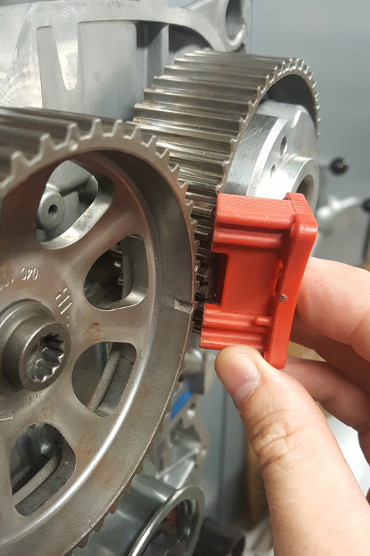
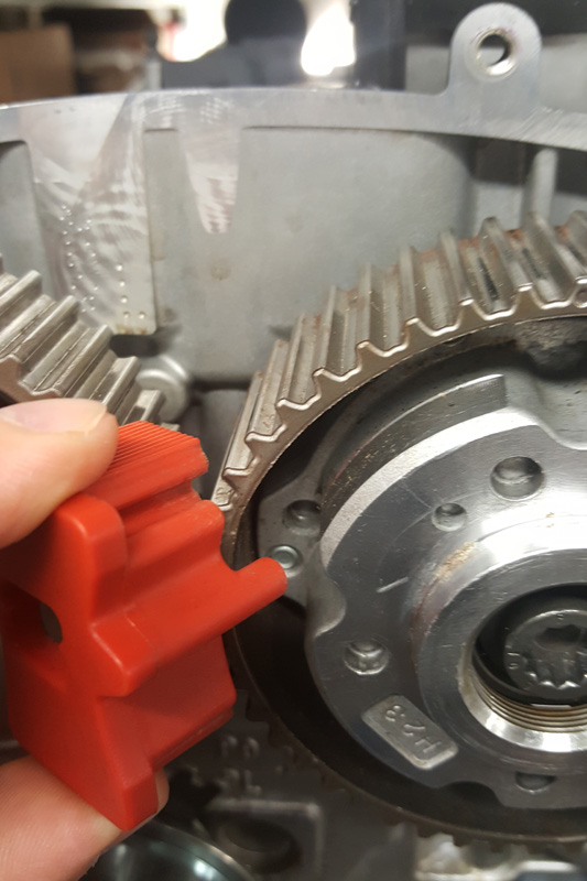
Replacing the timing belts presents new challenges for drive systems specialists. For many, it’s a first encounter with non-round pulleys. For all, it’s a procedure that must not be attempted without the correct set of tools.
Tools required and points to note
As the drive system positioning of the non- round pulleys is extremely important, specific tools are vital to the success of the belt replacement procedure. The Gates timing tool kit (GAT 5140) is required to complete this job correctly. An appropriate camshaft pulley holding tool is required (for example, GAT4844). A crankshaft holding tool is also essential (for example, GAT 5169). When replacing the timing belt, it is good workshop practice to replace the associated metal components at the same time. Gates PowerGrip Kits include belts as well as any appropriate tensioners and idlers.
The water pump is driven by a separate small timing belt without a tensioner. Gates supplies separate belt kits for both the timing belt and the water pump. Note that not all timing belts have a synchronising function.
Twelve-step procedure
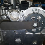
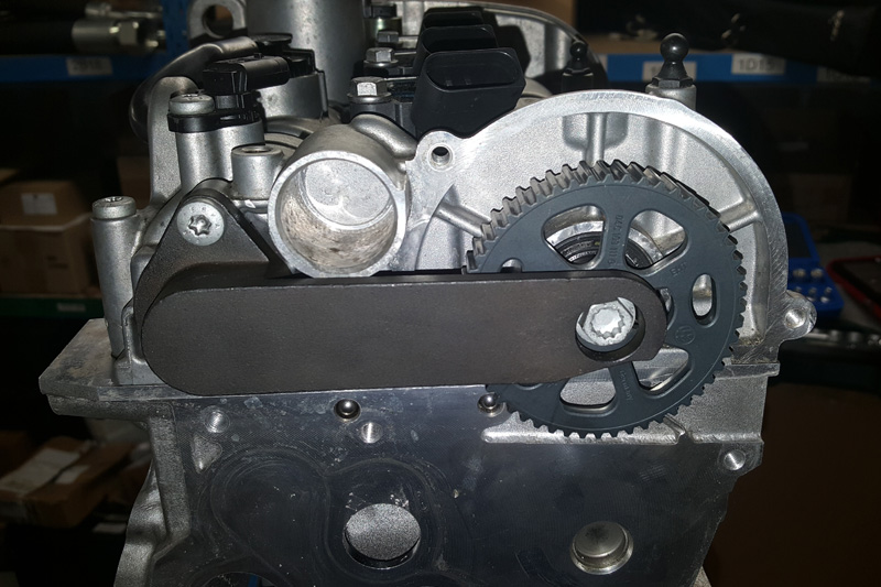
1. The first step is to put the engine’s first cylinder at top dead centre (TDC), then lock the crankshaft (locking pin on the side) and the camshaft at the rear.
2. Holding the pulleys in place, loosen the camshaft pulley bolts (right bolt behind plug). Loosen the exhaust camshaft pulley (left) from the conical axle; loosen the belt tensioner pulley bolt while holding the tensioner in place; rotate anti-clockwise (till the retaining lug is situated at the bottom of the slotted hole).
3. Remove the belt.
4. Replace the tensioner and the idler and fit the camshaft pulley locking tool. This will secure the location of the two camshaft pulleys. It is important that they remain in the exact position at which their non-roundness will work to the advantage of the engine (otherwise they will increase belt tension fluctuation rather than reduce it). Note that the dots on both pulleys (at +/- 3 and 9 o’clock (and 12 o’clock) will not line up perfectly.
5. Install the new belt (crankshaft, tensioner, camshafts and idler). Ensure that it is taut on the left side.
6. Remove the little camshaft pulley locking tool. Rotate the tensioner clockwise. The pointer must be 10mm past the notch (window).
7. Bring the pointer back to the middle of the window and torque the bolt to 25Nm.
8. Holding the camshaft bolts in place, lock them to 50Nm. Holding the bolts is a crucial part of the procedure. Install the crankshaft Micro-V pulley. Set a torque of 150Nm and then turn it through another 180 ̊ using the crankshaft holding tool.
9. Remove the locking tools. Rotate the engine, by hand, through two complete revolutions to TDC. Reinstall the locking tools (crankshaft and rear camshaft).
10. If reinstalling the tools proves impossible, restart the procedure from step 1.
11. If this does prove feasible, hold the camshaft sprockets in place and torque a further 90 ̊.
12. Bring the tensioner pointer back to the middle of the notch (25Nm).
Non-round benefits
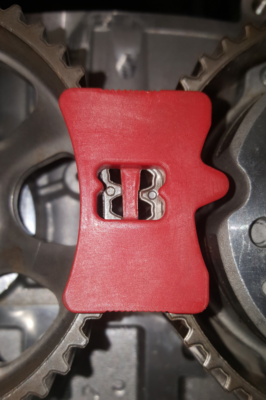
The non-round pulley design is, initially, difficult to spot. It only becomes obvious when slowly rotating the loosened pulley with your finger or rolling it across a flat surface. The design is vital to the ‘belt dynamic tension optimisation’ process, which is the key to the high performance and low emission qualities of this particular three- cylinder engine. During the intake or suction phase, the piston is moving down, while at the next stroke (compression), it compresses the mixture of air and fuel.
This is followed by strokes three and four – combustion and exhaust. These different strokes cause significant belt tension variation throughout the combustion cycle. This tension variation is countered by means of the non-round pulley design, which delivers a defined amplitude and phasing. The result: optimised belt tension.


