A calibration of the Lane Departure Warning System needs to be carried out for a number of reasons. Here, Autel takes us through an ADAS Volkswagen LDW Calibration.
There are a number of reasons this process needs to be undertaken. These are when:
- The front windshield camera is removed, replaced or reinstalled
- The front windshield is removed, replaced or reinstalled
- The chassis is adjusted
- The vehicle height sensor is relearned
Vehicle preparation
Set up and perform the calibration frame levelling procedure by following these steps:
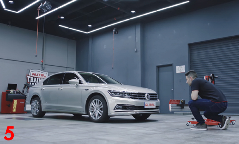
- Park the vehicle on a flat and level surface with its front wheels pointing straight. Ensure there are no objects within 3m of the front of the vehicle
- Turn the rear axle steering straight
- Bring the vehicle to a complete stop and turn off the engine
- The vehicle should not be carrying any load (passengers or cargo)
- Ensure the vehicle’s coolant and engine oil are at recommended levels and the gas tank is full
- Close all doors and ensure that all lights are turned off
- Adjust the tyre pressure to the recommended value
- Please ensure that the vehicle battery has sufficient power. Otherwise, connect a battery maintainer and avoid battery discharge
- For vehicles with air suspension, activate ‘Jack Mode’
- The windshield should be clean and the dashboard should be free of objects
- Ensure there is no reflection on the windshield (reflective objects can be covered with black cloth)
- Ensure the calibration area is well lit
- Attach the VCI to the vehicle and turn on the ignition (ignition on/engine off)
- Connect the diagnostic tool to the vehicle
- Tap ‘Diagnostic’, then ‘Auto VIN’ on the upper left of the screen to read the vehicle identification number and identify the vehicle model
- Select ‘ADAS Calibrate’, and tap the appropriate LDW calibration option
Note: the vehicle manufacturer may market this system by another name, and these vehicle preparation measures vary by vehicle and system. Be sure to follow the specific instructions detailed on the MaxiSYS to ensure accurate calibration.
Tools required
- Calibration frame
- Pattern board CSC0601/01
- Two wheel clamps with laser attachments
- Tape measure
Calibration stand set-up
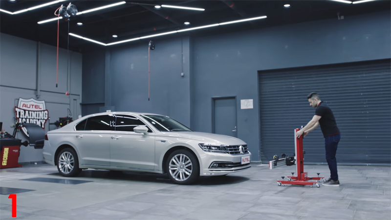
- Move the calibration frame in front of the vehicle
- The floor must be level, and no pattern should be attached to the frame (Fig 1)
- Rotate the fine tuning bolt to align the marked lines
- Loosen the handle and rotate the fine tuning bolt until the scale value is zero (Fig 2)
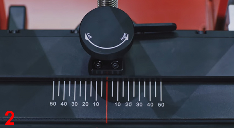
- Tighten the handle to secure the crossbar
- Align the pointer on the sliding plate with the zero marked line
- Tighten the bolt to secure the sliding plate
- Turn on the laser and aim the beam at the front centre of the vehicle
- Adjust the height of the crossbar so that it is levelled with the centre of the front wheel
- Carefully move the frame to ensure that the laser beam is pointed at the front centre of the vehicle
- Use tape measures to ensure that both sides of the crossbar are at the same specified distance to the centre of the front wheels (Fig 3)

- When the frame is in position, turn off the laser and rotate the bolts on the base until they are secured to the ground – do not overtighten the bolts
- Attach the two wheel clamps by placing the pawls outside the wheel rim, and tighten
- Ensure the wheel clamps are firmly secured to the wheels
- Insert the connecting shaft of the laser into the clamp port The laser calibration board should be facing the front of the vehicle (Fig 4)
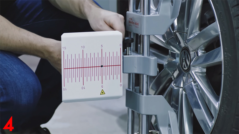
- Tighten the bolt to secure the laser
- Turn on the attached lasers and adjust them so the beams are on each side of the crossbar cover plate
- Loosen the handle and rotate the fine tuning bolt until the rulers on each side of the crossbar plate have the same value lit by the laser
- Tighten the handle to secure the crossbar
- Lift the cover plates on each end of the crossbar
- Adjust attached wheel lasers to control the up-and-down movement of the reflected laser beam (Fig 5)
- The reflected beam must shine on at least one of the scale boards of the laser boards
- Rotate the bolt left or right until the scale values lit by the reflected beam are the same on each side of the bar – the calibration frame is now parallel to the vehicle
- Close the cover plates on the crossbar
- Power off lasers on the attached wheel clamps and remove clamps from wheels
Lane Departure Warning System calibration
- Attach the specified pattern board onto the crossbar and tighten the bolt to secure
- Rotate the bolts on the base of the calibration frame
- Reference the bubble level to ensure the frame remains level. Loosen the height rulers so that it touches the ground
- Adjust the height of the crossbar to the height specified on the tablet
- Align the pointer with the corresponding value on the ‘B side’ of the height ruler
- Push the ruler back to the original position and secure it
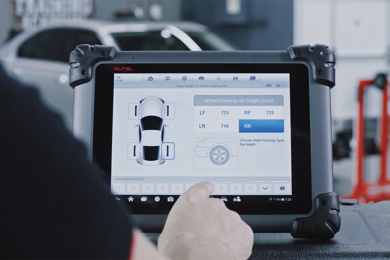
- Ensure the vehicle ignition is on, and tap ‘OK’ for each of the four wheels
- Then measure the height from the base of the wheel to the top of the wheel, and enter the values in the spaces provided on the tablet (Fig 6)
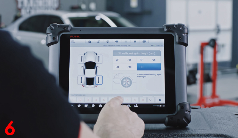
- When the message displays that the calibration is successful, tap ‘OK’
For more information online on MaxiSYS, click here.


