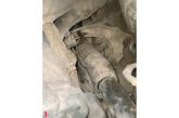
Many leaks are caused simply by vibration which causes refrigerant line connections to come loose, but refrigerant gas can also escape through the walls of the rubber hoses or at the drive shaft oil seal of the compressor.
NOTE: A leakage rate of between 50 and 100g of refrigerant per annum is normal.
In modern systems using R134a refrigerant, the leaks can be difficult to pinpoint as the synthetic refrigerant oil does not appear as an oily residue at the leakage point.

If an air conditioning system requires frequent charging, a leak test should be carried
out. If the source of the refrigerant leak cannot be found through visual inspection, there are various other methods available.
Preparation for leak testing
The refrigerant circuit must be under pressure when performing a leak test. If the air conditioning system is still operational there should be sufficient pressure in the circuit (at least 3.5 bar), to carry out an effective leak test. If the system charge is too low, the refrigerant will need to be recovered.
NOTE: If the system is empty, DO NOT charge it with refrigerant, carry out leak testing with oxygen free nitrogen (OFN).
Areas to check
a) All connections and pipes
b) Compressor drive shaft
c) Compressor service valves and sealing gaskets
d) Condenser and evaporator matrix tube ends
e) Receiver/drier or accumulator/drier connections
f) Pressure switches
g) Spring lock coupling connections
h) Hoses
Leak testing using oxygen free nitrogen (OFN)
Nitrogen has a molecular structure which makes it suitable to find most leaks, and in addition it is reasonably priced.
IMPORTANT: DO NOT exceed the recommended pressures (use a pressure regulator) and DO NOT operate the air conditioning system with oxygen free nitrogen (OFN) in the refrigerant circuit.
 Testing
1) If the air conditioning system is still operational, recover the refrigerant.
2) Connect the cylinder of OFN to a service connector, component or line, using a suitable adapter.
3) Open the cylinder valve to pressurise the circuit to approx. 10 to 15 bar (sufficient for leak testing purposes), and close the valve.
4) Using a commercially available bubble dye solution, spray the suspect areas to locate the leak.
5) Release the OFN from the circuit before attempting any repairs.
Leak testing using an electronic tester
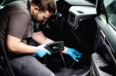
Electronic leak detectors can be particularly useful in finding very small leaks.
Testing can be difficult in drafty conditions; it may be necessary therefore to shelter the suspected leak area in order to prevent any draft blowing the refrigerant gas away. If the surrounding air is contaminated with refrigerant gas, the leak tester will indicate gas all the time. It may therefore be necessary to ventilate an area to be leak tested.
- Ensure that the air conditioning system is charged, a partial charge, approximately 225g is sufficient.
- Pass the probe under the suspected leak area starting at the highest point in the circuit (refrigerant gas is heavier than air).
- When a refrigerant leak is detected, the tester will emit an acoustic signal. The signal and intensity will change as the concentration of refrigerant gas increases or decreases.
- If the leak cannot be detected with the air conditioning system switched off, start the engine and operate the system to build up system pressure.
NOTE: With a partially charged system it is advisable to run the air conditioning system for only a short period and not to exceed engine idle speed, as there may be insufficient oil to sustain lubrication of the compressor.
Leak testing with bubble dye solution
For basic leak detection (for instance in the area of connections) a bottle of commercially available bubble dye solution can be used. The bubble test method is a cheap form of leak testing and can assist in finding a variety of leaks, but it is not as reliable as other leak testing methods.
- Ensure the refrigerant circuit is fully charged.

- Swab the suspected area with the solution.
- Check for bubbles which would indicate a leak.
- If the leak cannot be detected with the air conditioning system switched off, start the engine and operate the system to build up system pressure.
NOTE: With a partially charged system it is advisable to run the air conditioning system for only a short period and not to exceed engine idle speed, as there may be insufficient oil to sustain lubrication of the compressor.
Leak testing with an ultraviolet lamp
To make leaking refrigerant visible under ultraviolet light, the refrigerant gas is mixed with a special dye which is added to the refrigerant. The highlighting effect produced by exposure to the light of an ultraviolet lamp makes it easy to locate refrigerant system leaks.

NOTE: Leak testing dye may have already been added to the system by the vehicle manufacturer.
The dye can be added to the refrigerant system during repair, or during the evacuation process, depending on the equipment available. Using an injector, dye can also be added to the low pressure (suction) side when the system is being charged. The dye attaches itself to the refrigerant oil and even if the refrigerant is removed and the system is re-charged, the dye will still remain in the system.
- Following the manufacturer’s instructions add the amount of dye stated to the refrigerant system.
- Start the engine and operate the air conditioning system.
- Shine the ultraviolet lamp around the suspected areas.
- The leak will be visible when the dye is exposed to the ultraviolet lamp.
CAUTION: Excessive ultraviolet light can damage eyesight. When using ultraviolet light always wear suitable safety goggles that screen out ultraviolet light.
Autodata Online
All information used in this article is taken from the ‘Technical Topics’ section of Autodata’s Online 3.
Autodata is Europe’s leading provider of technical information for automotive professionals. Covering over 15,000 models from 80 vehicle manufacturers, Autodata’s systems ensure that professional workshops have access to the most accurate, relevant and up-to-date manufacturers’ information needed for service, repair and diagnostic work, in the shortest possible time.

