We begin where we left off in last month, as Steve Smith, Automotive Application Specialist at Pico, continues his task of correcting a camshaft correlation error on a Toyota Camry…
Thanks to our colleagues at Toyota UK, we located another vehicle we could use for comparison measurements, in the form of a Lexus RX350. While this is not a direct comparison, the engine codes were the same, (2GR-FE) and as the saying goes, ‘you have to make the most of what you’ve got’.
Once again, the same procedure applied to the donor vehicle. The fault codes were checked (all clear), VVT operation was confirmed using the active test feature of the scan tool, and finally, the VVT controllers were disconnected to ensure that all camshafts returned to their default position. This ensured that we, as near as possible, were ‘comparing apples with apples’ beyond a reasonable doubt.
Starting with Bank 2 of our donor vehicle (Fig 5), we can see that the correlation between camshafts and crankshafts are comparable with the customer vehicle.
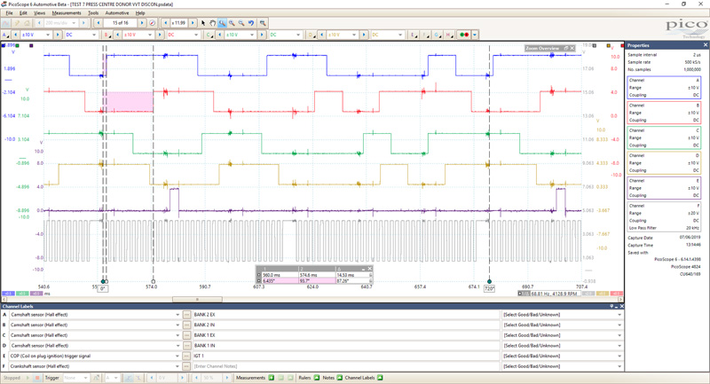
Bank 2 Exhaust Camshaft displayed 6.435° of crankshaft rotation after our 0° rotation ruler and Bank 2 Inlet at 93.7°. Taking all the variables into consideration, these values are a near perfect match to our customer’s vehicle (Bank 2 Exhaust 6.458° and Bank 2 Inlet at 94.84°).
The process for Bank 1 camshafts of the donor vehicle is repeated (Fig 6), returning values of 184° for Bank 1 Exhaust and 216.1° for Bank 1 Inlet. Here, we finally have the error we were looking for and, more importantly, this matches the fault reported by the PCM (P0016 – Camshaft Position Correlation (Bank 1 Sensor A)).
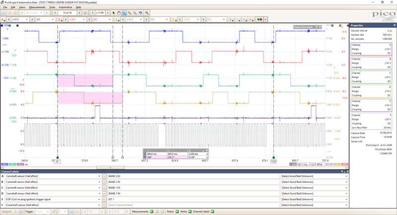
But how could this be possible when the static valve timing check confirmed no error? Without a doubt, we have a sufficient deviation in the correlation between vehicles for Bank 1 camshafts. Given that our donor vehicle has no camshaft correlation fault codes, we can conclude that our customer’s vehicle Bank 1 camshafts are retarded by approximately 4°. How can we have a deviation of almost 1° (0.85°) between Bank 1 inlet and exhaust camshafts?
This could be ‘stretching’, or a fluttering timing chain, worn timing sprockets, gears, tensioners, slippers, or even oil pressure.
I can confirm there were no oil pressure symptoms and no timing chain/engine rattle throughout the entire coolant temperature range. In hindsight, I wish I had measured the oil pressure, but as you will see, it proved not to be relevant.
At this stage, I don’t have all the answers, but whatever this is, it has the ability to deviate the camshaft and crankshaft correlation by values that differ between camshafts and Banks. Looking at the pick-up ring for our crankshaft sensor, we have 34 teeth (36-2) to denote one engine revolution (360°).
Sticking with 36 teeth to simplify the maths, 360°/36 teeth = 10° of crankshaft rotation for one tooth and one gap of the pick-up ring. This is the best resolution (minimum crankshaft movement) we obtain when trying to determine the amount of crankshaft rotation via the scope using tooth count alone. However, by using the rotation and time rulers, we can measure between the pick-up teeth, giving us infinite resolution and the ability to detect minuscule movement of the crank and camshafts.
With this information in mind and access to the original VVT controllers (with integrated camshaft timing gear), we have 36 teeth on the inlet camshaft timing sprocket and therefore 18 teeth on the crankshaft timing sprocket. 360° of engine rotation/18 teeth of the crankshaft timing sprocket = 20° of engine rotation for every tooth of the crankshaft timing sprocket.
20° of crankshaft rotation = 10° of camshaft rotation, which could be detected by counting crank sensor pulses alone. However, our camshafts are retarded by approximately 3 to 4°, which can only be measured, as mentioned previously, via the rotation and time rulers.
We can, therefore, conclude that our primary timing chain (crankshaft to inlet camshafts) has not jumped a tooth, as our dynamic valve timing check would return a camshaft error of 10° for all camshafts, not just Bank 1 inlet.
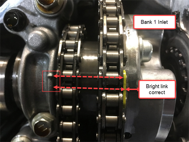
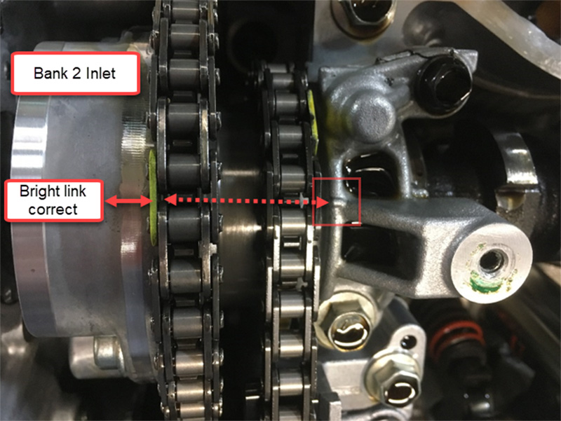
We could, however, have a timing error between Bank 1’s secondary timing chain connecting the inlet to the exhaust camshaft, although the technician confirmed the bright links of the timing chain to be aligned with their respective markers to all timing gears.
Remember, both Bank 1 camshafts are retarded by a minimum of 3.15°! Now, where do we go?
Back to basics, once again
We removed the cam covers and checked the static valve timing for alignment. The initial inspection confirmed good alignment of all timing marks with the visible bright links located correctly. However, to throw a curve ball in here, if the engine was rotated numerous times clockwise, then shuffled back anti-clockwise before settling clockwise (in order to qualify the static valve timing), the timing marks looked suspicious and inconclusive for the Bank 1 inlet camshaft.
The Bank 1 inlet camshaft timing is inconclusive given that the alignment drifts with repeated engine rotation (Fig 7). The Bank 2 inlet camshaft timing has conclusive alignment with repeated engine rotation (Fig 8).
Based on the evidence gathered, we decided to remove the engine and inspect the timing chain assembly.
Results
Unfortunately, it was not possible to visit this engine during the repair procedure or postfix, however, Fig 9, 10 and 11 speak volumes.
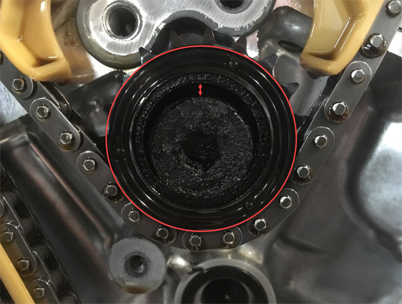
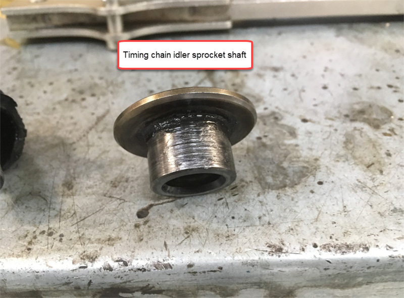
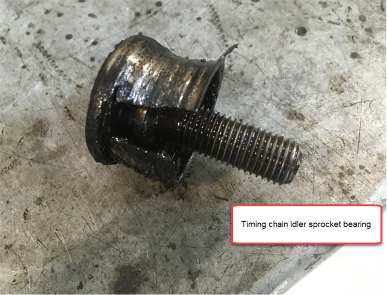
In Fig 9, we have excessive eccentric wear of the timing chain idler sprocket, allowing the tension between Bank 1 inlet camshaft and the idler to periodically ‘relax’ (depending on engine load), which resulted in the camshaft timing deviation.
Notice the debris and deposits in the oil residue about the inner circumference of the idler sprocket. Removal of the idler confirmed excessive ‘shell’ bearing wear due to lubrication starvation from a blocked oil passage to the idler shaft. The passage was contaminated with the identical residue found around the idler sprocket, which begs the following question:
Did the idler bearing fail and block the oil passage or did oil contamination block the passage resulting in bearing failure? Given that we have no vehicle history, I would go with the latter.
Confirmation of repair
While we could not attend the vehicle postfix, I have liaised with the team involved in the repair and can confirm that the vehicle has been returned to the customer after extended road testing without any further issues (MIL Light remains extinguished and engine faults codes are clear).


