When approaching electric vehicle (EV) diagnostics, it’s easy to focus all your efforts on the high-voltage system. However, Pico technician Ben Martins argues that the low-voltage system must also be carefully considered, particularly inputs like the resolver sensor. Here is why…
There’s no getting around it, electric vehicles (EV) are here to stay and will continue to grow in popularity as the shift from fossil fuels to electric becomes more apparent. The introduction of high voltage batteries brings with it new complexities and technologies that may be unknown to some. Understandably, training is imperative when working on these vehicles and information found online must not be used as a training replacement.
When it comes to EVs, people often get a little caught up on the high-voltage system. However, the fact is that the vehicle can’t operate at all without the various inputs and outputs from the low-voltage system. One such input is the resolver sensor.
The role of the resolver
The resolver sensor determines the position of the rotor, enabling the inverter to trigger the insulated-gate bipolar transistors (IGBTs) which allow the current flow to the correct winding. The resolver is a relatively simple device that has no moving parts, which makes it a typically reliable component.
However, even the most reliable parts can fail and when a resolver has an issue, it can cause several knock-on effects that can trigger additional fault codes unrelated to the resolver. Therefore, the ability to test them correctly is a must.
The trouble with testing resolvers is that ideally you need to check all three circuits at the same time. This is made more difficult as the circuits are floating with no common ground, which means that to truly visualise the signals, you have to use differential probes or an Automotive 4000-series PicoScope with floating inputs.
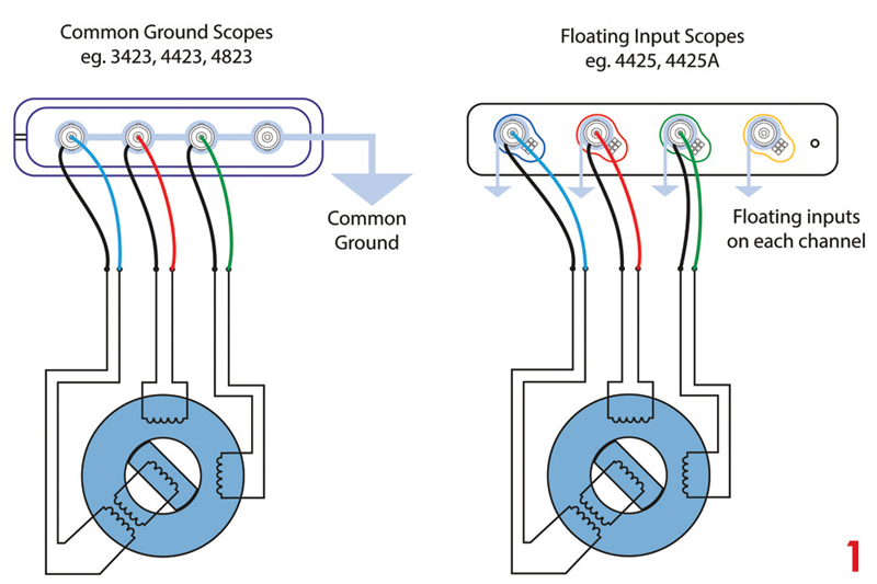
Just to clarify, it is only the 4425 and 4425A PicoScopes that have this floating input. Any other automotive PicoScope has a common ground, like most other available scopes. I have added an illustration (Fig 1/main image) to explain why you can’t use a common-ground scope to measure a resolver.
If you use a common-ground scope connected across all three circuits you will cause a dead short between them, which will introduce fault codes. If you use a single ground to chassis, the measurement won’t be useful as it will provide insufficient detail to verify the resolver.
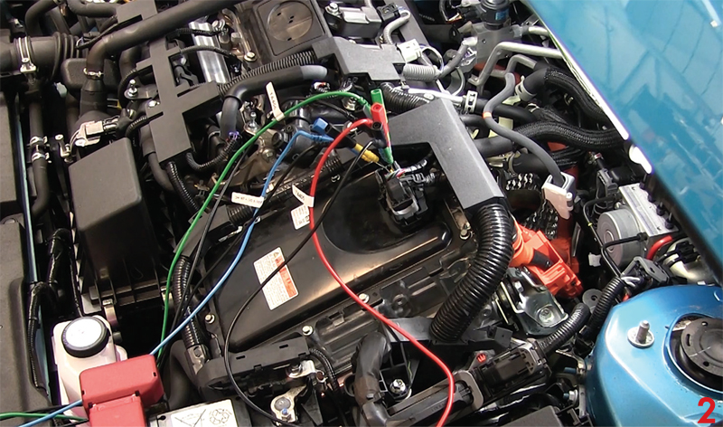
As I said previously, if you don’t have a PicoScope 4425A or 4425 you can use three differential input probes to test these resolver circuits (Fig 2).
How to test the resolver
Underneath it all, a resolver is a fairly simple sensor. Coils form a stator around the rotor, which is directly connected to the motor’s output shaft. The stator is formed from three separate windings, consisting of an exciter winding and two output windings.
An alternating current at around 10 kHz is passed into the exciter coil, which is then induced into the rotor. The sine and cosine windings are arranged 90° apart so that the amplitudes of the induced currents are dependent on the relative angle of the rotor.
The rotor is shaped with lobes (the number of which varies between manufacturers). These create a change in the intensity of the output winding, depending on the rotor position.
If you follow the guided test in PicoScope 7 Automotive, and connect as shown in the diagram, you would expect to see the pattern in Fig 3.
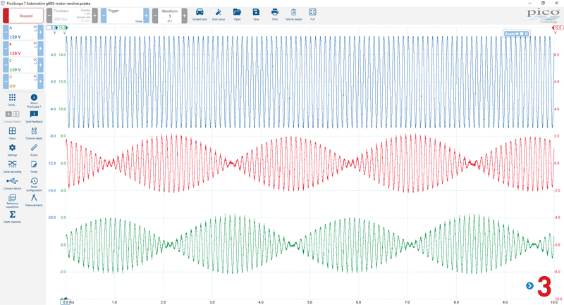
Even with this signal, though, it’s not easy to determine how the vehicle can establish the position of the motor. This is where having all three signals is vital, as we can introduce a math channel that removes the 10 kHz frequency created by the excitation coil to see the actual positioning (Fig 4). To understand the math behind the waveforms, please see the further guidance in the guided test, and for all things maths, please see the ‘Math is Cool’ section on the Pico forum.
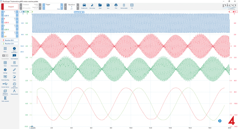
Another factor we have to consider is the number of poles present on the resolver, as this will dictate how many cycles there are for one rotation of the rotor. This is one of the many reasons why we should always use genuine parts, as the wrong resolver could lead to big problems!
I know it still isn’t clear how the position is determined, but it can be made simpler by plotting the sine and cosine waveforms against each other.
As you can see in Fig 5, a circle begins as each cycle completes. The confusing part comes when there are multi-pole resolvers with more than one cycle to complete one rotation of the rotor. This all depends on the number of poles in the stator and the number of lobes on the rotor. Unless we know the part number or remove the sensor and count the poles and lobes, there is no real way of knowing. However, from a diagnostic point of view, the information provided in this waveform is extremely useful in verifying the sensor’s output.