In the last instalment of our guide to Bosch’s KTS diagnostics software, ESI[tronic] 2.0, we looked at the diagnosis tab and mastering actuator tests. In this instalment, we’re testing out the built-in multi-meter and oscilloscope.
In the tenth article in our series, we’re going to introduce you to the added benefit of vehicle diagnosis with the built-in multi-meter or oscilloscope functions included in the KTS vehicle communication interface.
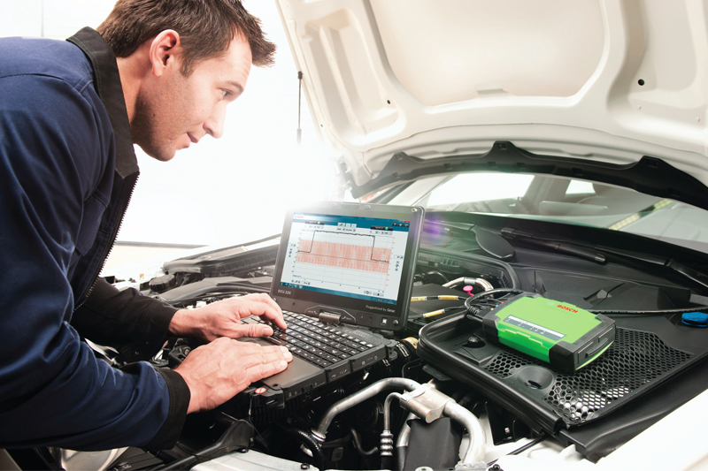
Alongside all of the other equipment required to effectively work on modern cars today, many technicians consider a graphing multi-meter or oscilloscope a luxury investment. The good news is, if you own a Bosch KTS 560, a single channel multimeter is included. While Bosch’s flagship tool – the KTS 590 – features a two channel multi-meter or oscilloscope which is all ready for you to use (Fig.1). The kit contains high-quality colour-coded test cables and probes, which use standard 4mm ‘banana’ type connectors.
First time fix rate
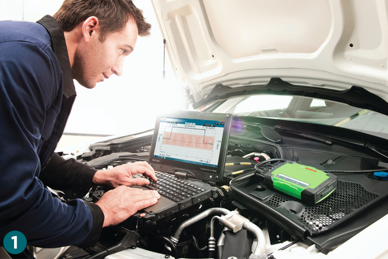
As we all know, a diagnostic trouble code (DTC) will often only give guidance to the general area of a system that is suspected to be faulty or out of range. Once a DTC is read from the error memory of a control unit, a robust fault-finding process is required to test the suspected component and its associated electrical circuit. In Bosch ESI[tronic] 2.0, there are many service information system repair instructions linked to an error memory code that will suggest a direct measurement needs to be made of the voltage supply, earth path, signal/command wire or component resistance in the system (Fig.2).
These values can be tested using the Bosch KTS multi-meter or oscilloscope, along with ‘guided’ fault-finding instructions and technical data. This added confidence in your results can lead to a dramatically improved first time fix rate.
For this article, we’ll concentrate on the multi-meter and oscilloscope functions of the KTS 590. Remember that if you have a KTS 560, there is no scope capability built into the VCI. For technicians that use a separate oscilloscope – such as the Bosch FSA 500 or FSA 720/740 series – then the KTS 560 is perfectly suitable for multi-meter use.
KTS multi-meter functions
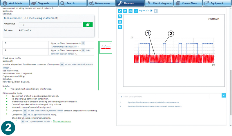
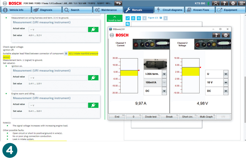
To get started, let’s take a look at the Bosch KTS multi-meter functions that can be used alongside the ESI[tronic] 2.0 vehicle diagnostic program. When the multi-meter is accessed via the main menu (Fig.3) a new window will appear on-screen with the multi-meter display and measurement selection options. Now you can overlay the multi-meter results screen over ESI 2.0 and see the serial diagnostic data and direct measurements side-by-side (Fig.4).
The test results will be wirelessly displayed on your PC screen, with the measurements taken by the probes attached to the KTS VCI connected to the vehicle. The readings can be shown in a numerical form, with a useful bar graph, or in a graphing trace format, with up to a minute shown across the screen for added convenience.
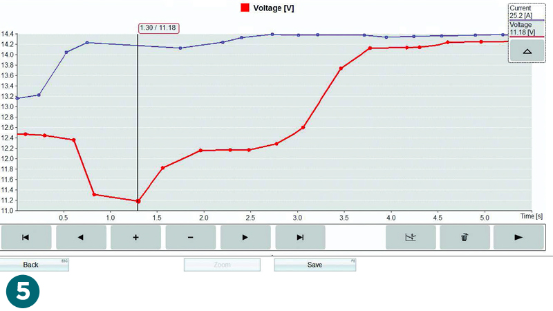
Another great feature is that, just like the actual value time profile display in ESI[tronic] 2.0, the multi-meter graph can be paused, reviewed, saved and printed (if necessary) for reference (Fig.5) – also showing battery voltage and current upon starting the engine.
For voltage and current readings, we have the choice of DC, AC or EFF (root mean square) settings on both channels and resistance measuring up to 1 MΩ on channel onw. You can connect a Bosch amps clamp with adapter for non-intrusive current measurements to be displayed on screen. A really useful additional feature of the KTS multi-meter is the circuit break and short circuit function, which you can configure to emit an audible warning signal when you conduct a wiggle test on the suspect harness to help you find wiring faults along a loom.
KTS Oscilloscope
The Bosch KTS 590 two channel oscilloscope functions can be used for even greater in-depth testing of electrical systems and components. The beauty of using an oscilloscope is that it opens up a whole new dimension of system diagnosis by presenting you with an accurate graphical representation of voltage over time. This means you can see in detail what is actually happening in an electrical circuit in real time.
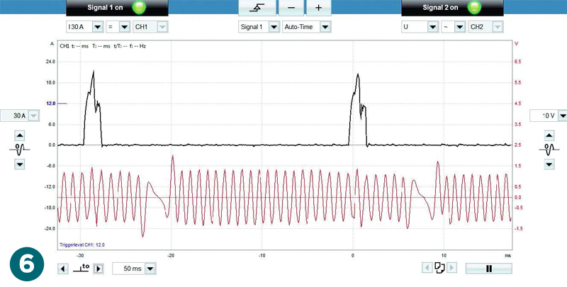
Fig.6 shows a PD injector and crankshaft sensor signal. Opened from the main menu, the oscilloscope screen can be viewed alongside the ESI 2.0 program and offers many customisable settings that enable you to effectively capture and display the test results you need.
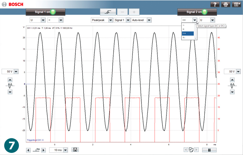
Trigger points can also be set to ensure that signal recording starts where you want it to, while waveform display options can be used to get the best results. There are too many options to describe them all here, but if you hover your cursor over any icon or soft key a ‘tool tip’ pops up with a description (Fig.7).
The time base for both channels can be set between five microseconds and one second across the screen. The safe continuous input voltage to the VCI is a maximum of 60V and the scale of measurement in voltage can display from 200mV (20mV/division) up to 200V (20V/div). The amps scale can also be selected between 30A and 1,000A in the current measurement. If you pause the oscilloscope recording the buffer memory holds the previous 25 screen captures, which can be scrolled through and reviewed – an essential feature if you’re searching for an intermittent fault.
If you only want a single channel measurement, then the blue and yellow cables can be used for potential free testing when the black earth cable is connected to channel two. This set-up can be particularly useful for testing both signal wires of an inductive speed sensor, for example. When a signal is being collected, the ESI 2.0 oscilloscope software automatically starts to calculate the specific signal on/off times as well as the frequency of the waveform if it is a repeated signal such as a pulse width modulated (PWM) duty cycle. This is really useful if you are checking the command signal to a component, such as a radiator fan control module.
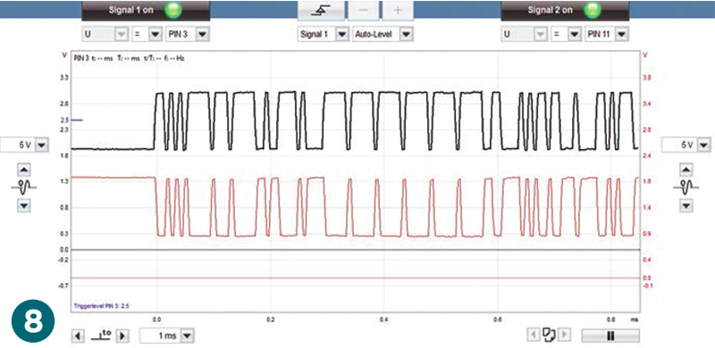
Another benefit of the oscilloscope is the ability to choose the channel option for signal acquisition via the coloured test cables connected to the channel inputs of the VCI. Additionally, you can switch to the ‘PIN’ input option, where the signal will be taken from the communication pins of the 16 pin OBD socket that will already be connected to the car. The earth pins 4 and 5 and power supply pin 16 are not available to scope this way, but any of the other pins are (depending on the vehicle configuration). For example, a single wire ‘K’ line on pin 7 or a CAN Bus signal on the traditional pins of 3 & 11 or 6 & 14 could be ‘internally’ tested (Fig.8). This can be a very quick and easy way to investigate if any control unit communication problems occur.
Next instalment we will look at the maintenance and equipment tabs.