Pico Technology charts the rise of the three-phase motor in powering passenger vehicles and how its latest tool is helping technicians perform more accurate low-resistance testing.
Over the last 20-25 years, consumers and governments have pushed for increasingly efficient vehicles with reduced emissions. High-voltage drivetrains, with their powerful and robust three-phase motors, are more than twice as efficient as their internal combustion engine counterparts and a key part of the solution. However, those were not the first or only motor-driven components to replace their older, inefficient, power-hungry alternatives. The switch from hydraulic to electronic power steering marked the start of the trend. Since then, we have also seen the introduction of three-phase motor-driven air conditioning compressors, air blowers, fuel pumps (delivering increased pressures), oil pumps, exhaust gas recirculating valves, turbo actuators, valvetrain lift/timing mechanisms, etc. In short, powerful, and efficient, three-phase motor-driven components have proliferated within our vehicles.
Motor winding resistance has a direct effect on motor efficiency. In high current systems, say over 100 amperes – such as those in high-voltage powertrains – the heat energy caused by 50 milliohms of excess resistance is equivalent to 500 watts (0.050 ohm x 100 amperes x 100 amperes). This substantial heat output represents wasted energy, damages circuits and components, and shortens motor life. Therefore, excess motor winding, control, and power supply circuit resistances are obvious root causes of performance issues or component failures that we need to diagnose. The question is, how?
Not so long ago there were multiple options, as the required measurement accuracy was lower due to the circuit resistances being generally higher with a wider tolerance. For example, with a relatively low power single-phase motor, the preferred option would have been to directly measure voltage and current whilst it was operating under load, and then use those to work out the winding resistance. Alternatively, most multi-meters have reasonable accuracy and resolution at resistances from one ohm to one megaohm. As such, you could have disconnected the motor and directly measured its winding resistance to a just-about-acceptable accuracy using a reasonable-quality multi-meter.
With today’s three-phase motors and their complex control systems, the previously preferred resistance measurement option would require three high-voltage differential probes and three high-current amps clamps, all measuring simultaneously. That type of measurement takes an increased investment in equipment, a considerable effort to set up and perform, and exposes technicians to the hazards of working on live high-voltage systems. In addition, unless the motor load and speed and all other system and environmental conditions are held perfectly constant, the temperature and, hence, the resistance of the motor windings, will change during operation. Given the typical winding resistances are low (in the order of tens of milliohms), it is very expensive, difficult, potentially risky, and time-consuming to use this method to reliably calculate winding resistance in these motors.

Could we use a multi-meter to measure the resistance instead? There is the aforementioned need to measure milliohms-level resistance values with an order of microohms of resolution. In addition, there is a requirement to mitigate the effects of temperature, additional resistances arising within test leads and from test connections, as well as electromotive forces arising from connections between dissimilar metals. These factors all rule multi-meters out from being suitable milliohm measurement devices.
New tool
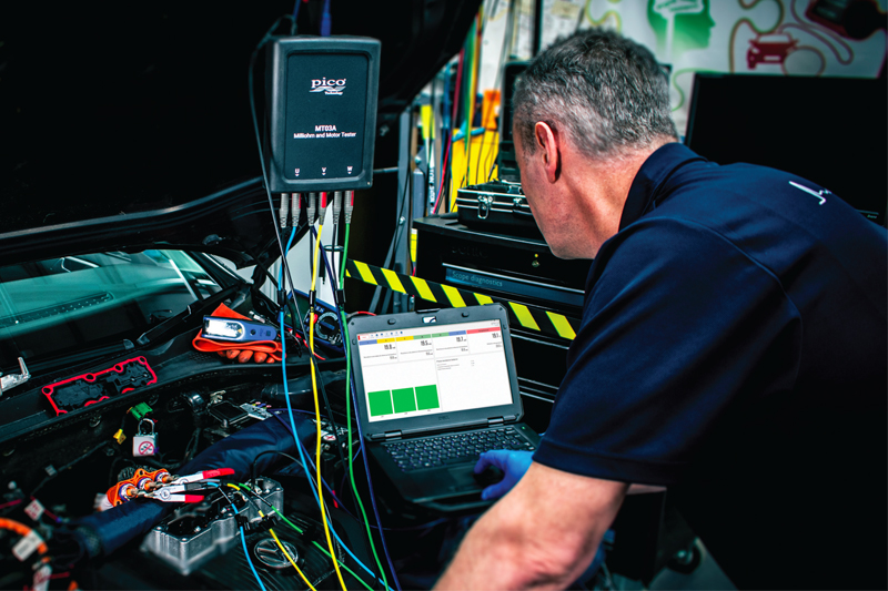
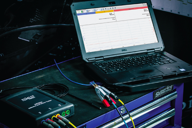
According to Pico Technology, its new MT03A Milliohm and Motor Tester is capable of changing the way low-resistance testing is performed. It uses simultaneous temperature and resistance measurements to rapidly check all three winding resistances in under a minute. During testing, temperature coefficient compensation, four-wire connections, and kelvin clips are used to mitigate against the effects of temperature, test lead resistance and test connection resistance. In addition, the current through each winding is reversed during testing to counteract the electromotive forces arising from dissimilar metals. The results are quick and reliable milliohm measurements with microohms of resolution.
As well as accurate low resistance measurements through all electrical components, the MT03A can be used to carry out earth-bonding testing. Earth bonding is an electrical mechanism employed on highvoltage machinery and equipment to ensure that no parts of the machinery can reach a high potential (voltage) in the event there is a short from either the positive or negative highvoltage system bus to another part of the vehicle. This makes it a key tool for checking the functional state of an electrical vehicle. As the device boasts a minimum test current of 200 mA, it complies with UN ECE R100 regulations for earth-bond testing.


