Nissens guides readers through the diagnosis of a faulty EC sensor
Although on first thought the engine coolant temperature sensor seems a relatively simple component, it plays a vital role in the overall engine management system, ensuring not only the proper working parameters for the engine and protecting it against overheating, but also the engine’s performance, particularly in regard to exhaust emissions and fuel consumption. A faulty sensor can therefore provoke various symptoms related to the engine’s operation, which can lead to problems with other parts or systems.
Background
The EC temperature sensor maintains the correct parameters within the engine cooling system, by monitoring and controlling the coolant’s temperature. However, many modern engines also utilise the sensor’s output signal for other engine functions, including to:
- Adjust the fuel injection
- Regulate the charge pressure
- Set the exhaust gas recirculation quantity
- Switch between cooling circuits (small and full circuit)
- Switch or control the main or auxiliary cooling pumps
- Activate/deactivate the start-stop system
The signal may also be used by other control units such as the heating, ventilation and air conditioning control unit and the air conditioning compressor, that may influence the engine load.
The EC sensor uses electrical resistance to measure the coolant’s temperature, and there are two main types. The most popular is the NTC (negative temperature coefficient) that decreases resistance and the generated voltage when the temperature increases, but older applications may use PTC (positive temperature coefficient), which increases resistance and the generated voltage when the temperature increases.
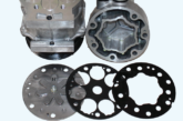
The readout voltage signal generated by the sensor is forwarded to the engine control unit (ECU), which can then make adjustments to the engine’s and related systems’ performance. Depending on the car’s design, there may be more than one sensor applied by the engine. Typically, the sensor is mounted on the coolant inlet on the engine block or the cylinder head.
Symptoms of a malfunctioning EC sensor
- Check engine or service light
- Engine in limp mode
- EC system-related fault codes stored by ECU
- Increased fuel consumption
- Increased engine emissions/smoking
- Uneven/improper idling
- Lowered engine performance
- Engine stalling/starting issues
- Engine overheating
- Radiator fan does not start/stop
- AC compressor does not start

Recommended troubleshooting
- Various fault codes and sensor-related symptoms may have their root causes in other component failures. So, before blaming the sensor for breaking down, inspect other cooling system components thoroughly.
- Inspect coolant level
- Inspect the head gasket is intact/not leaking
- Inspect the function of the EC system thermostat
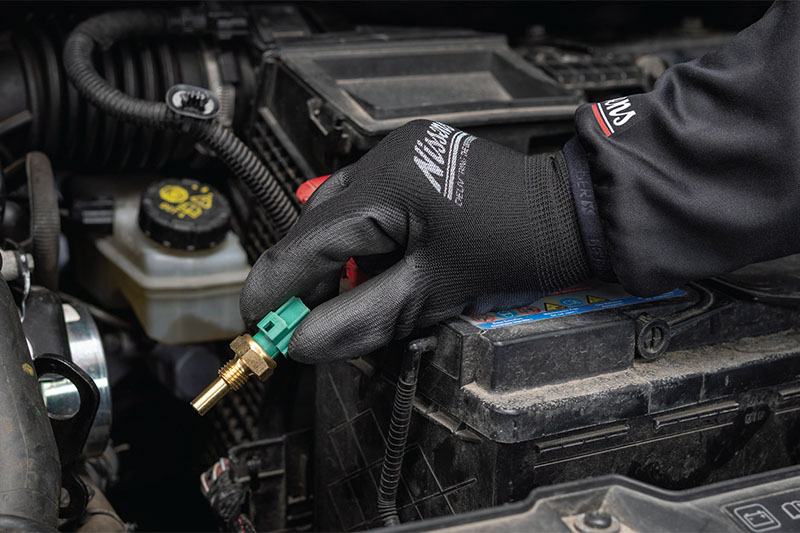
- Inspect the sensor’s electrical connection. Possible faults may cause signal interruptions, provoking faulty code generation and erratic temperature readings. Inspect the sensor’s wiring, ensure the connected socket fits correctly, the connector and pins are intact, and are free from moisture or corrosion.
- Perform OBD scanning to find related trouble codes. Read the OBD’s live data to control the coolant temperature reading from the sensor.
- Using a multimeter, inspect the function of the sensor and the voltage signal sent to the ECU. Determine the sensor’s signal and ground lines. Connect the negative wire of the multimeter to the chassis ground and the positive wire to the sensor’s signal line. Start the engine and inspect the voltage changes depending on the temperature. A healthy NTC sensor should read around 2-3 V onacoldengineandabout0.5V ata warm engine. A healthy PTC sensor should read 0.6-0.8 V on a cold engine and 1-1.5 V on a warm engine. For both sensor types, 0 V readings may indicate power supply interruption or a short circuit to the ground, and 5.0 V will mean an open circuit. Always consult the vehicle documentation to find the type of sensor and its correct temperature vs voltage values.
- Disconnect the sensor’s plug and inspect if there is the correct voltage supply from the sensor (typically 5 V)
- Having the sensor unplugged, inspect the sensor’s internal resistance, which should be temperature-dependent so place it in water and read the changes in the resistance. Consult the results with the given sensor’s type and model documentation.
A healthy sensor should read:
in20° >NTCtype:2200-2800Ohm, PTC type: 28-300 Ohm
in80° >NTCtype:270-300Ohm,PTC type: around 400 Ohm