febi takes a detailed look at crankcase emissions, as well as outlining some common cases where the emissions ventilation system fails.
Crankcase emissions are produced as a result of the combustion process of the internal combustion engine. These are a by-product of this process, with exhaust gases escaping from around the piston rings and into the crankcase. The overall volume of these gases varies depending on cylinder pressure, piston ring pressure and component wear. The elements found in these blow-by gases include wear particles, oil, fuel, gas and air. The specific composition of the elements varies depending on the fuel, engine configuration, engine speed and load, and maintenance history of the engine.
How do they work?
These blow-by gases are typically made up of hydrocarbons (HC), carbon monoxide (CO), carbon dioxide (CO2), nitrogen oxides (NOx), water vapour and traces of sulphates and aldehydes. The crankcase hydrocarbon emissions are normally about 3 per cent of the total exhaust emissions tested at the midlife of the engine. However, due to piston ring tolerances, crankcase hydrocarbon emissions can increase to 20 per cent of the total hydrocarbon emissions.
If not controlled, these gases can contaminate the lubricating oil, resulting in sludge. The crankcase can be pressurised – causing oil seals to fail – which, in turn, can lead to oil leaks, as well as having an impact on the starting and the smooth running of the engine and exhaust emissions.
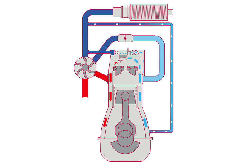
Positive crankcase ventilation is a system that was developed to regulate the internal engine pressure and remove harmful vapours from the internal combustion engine. This prevents these vapours from being expelled into the atmosphere.
The PCV system does this by using a manifold vacuum to draw vapours from the crankcase into the intake system. The separated droplets of oil flow back to the oil sump and the cleaned blow-by gases are recirculated into the intake area. They are then carried with the fuel/air mixture into the combustion chambers, where they are burned. Every car has some form of crankcase ventilation system, which can consist of several basic parts including hoses and connectors, an oil separator and a ventilation valve. These components can be separate or built into the engine.
The most typical defects of a crankcase ventilation system are a rupturing of the rubber valve membrane and blocked or split hoses or ducts. This leads to high oil consumption, burning oil, loss of power, misfiring, and high carbon deposits. Early signs of a failing PCV system include whistling noises from the intake, blueish smoke in the exhaust, high oil consumption, and thick white or yellow residue under the oil cap. However, many of these symptoms can go unnoticed or be misdiagnosed – mistaken for other issues or components. Here are a few common crankcase ventilation system examples:
Land Rover Freelander TD4 and Range Rover TD6
The engine oil is leaking – usually from the dipstick tube, because the dipstick has been pushed out under crankcase pressure. Other symptoms include lack of engine power (the engine will not increase in speed), black or blue exhaust smoke and excessive oil consumption.
These are caused by a blocked crankcase breather filter – this filter is located in the depression control valve assembly, which is fitted to the camshaft cover. Replace the blocked filter and the complete breather valve assembly, clean any excess oil leaks, and test.
Various Volkswagen, Audi, SEAT and Skoda models, fitted with the 1.8 or 2.0 FSi/ TFSi engine
The engine crankcase is maintained in a constant vacuum while the engine is running. The engine is equipped with a crankcase breather valve installed on the rocker cover, directly connected to the intake manifold.
The crankcase blow-by gases are separated into two stages. Firstly, the primary oil separator in the oil filter housing removes the majority of engine oil from the gases. Secondly, the separator on the rocker cover removes the remaining engine oil vapour from the gases.
The turbocharged variants have a more sophisticated pressure control system. A two-stage pressure control valve is located on the rocker cover. When the intake manifold vacuum is present, blow-by gas flows into the intake manifold. When turbo-boost pressure is present, the one-way valve in the breather valve assembly closes and blow-by gases flow into the valve cover.
Over time, contamination causes reduced air flow and the rubber membrane can split in the oil separator. Additionally, the sealing joints between the breather hoses become dry and do not seal.
The faulty oil separator or hoses cause the following symptoms: engine idle speed to fluctuate and stall, whistling noises from the engine at idle speed and increased oil consumption.
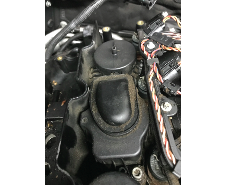
Various BMW models, fitted with the N20 engine
In earlier BMW engines, the crankcase ventilation system was designed to be outside the engine. In the N20 engine – and many others – the crankcase ventilation valve is built into the top of the rocker cover.
The blow-by gases pass through the opening in the intake side, with spring tab separators in the rocker cover. The oil in the blow-by gases is separated by the spring tab separators and flows along the walls, down through a non-return valve and back into the cylinder head. The blow-by gas cleaned by the oil now passes into the air intake system.
The most typical defect of this crankcase ventilation system is a rupture of the rubber valve membrane. The rocker cover, which is continuously exposed to heat cycles and vibration, can crack and leak. The oil separator galleries can clog with oil particles and residue.