The mechanical synchronisation of the crankshaft and camshaft is of the utmost importance for the operation of an internal combustion engine. febi explains how its sensors can help.
With the introduction of basic engine management and transistorised ignition, improving the reliability with the reduction of moving parts and more precise measurements was required. The development of solid state electronics improved, which included the common use of crankshaft sensors, quickly followed by the use of camshaft sensors. These sensors measure the speed and position of the cam and crankshaft. Their signal is processed by the engine management ECU to improve the accuracy of the ignition and fuel timing.
The two main technologies used in these sensors are typically of a hall or inductive type. The operations of these sensors are fundamentally similar, although the construction can vary depending on the type of sensor and its intended use by the vehicle manufacturer.
Inductive sensor
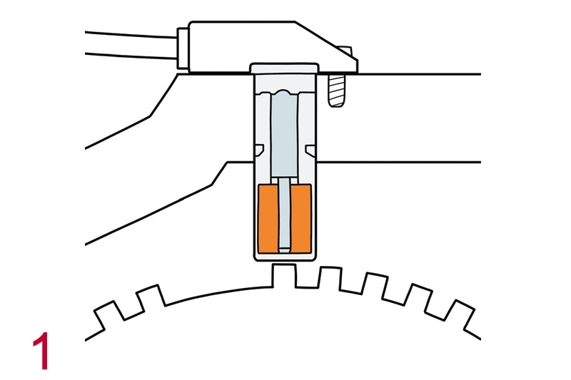
During operation the inductive sensor, as a result of the inductive effect in the sensor’s coil, produces an oscillating voltage. When the ferromagnetic trigger wheel (with teeth) passes close enough to the soft iron core of the sensor, the magnetic field surrounding the coil is changed. In the coil, a voltage is created which is proportional to the strength and rate of change of the magnetic field. One complete oscillation is produced for each tooth that passes beside the sensor (Fig.1).
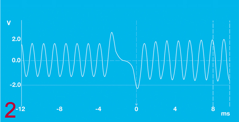
The AC voltage signal produced by the sensor depends on the speed of the trigger wheel and the number of turns in the coil. An output voltage between one to two volts could be expected at engine cranking speed, however as engine speed increases this will be more. The output voltage signal produced is of a low energy, so could easily be degraded by stronger external signals, such as the ignition system (Fig.2).
Hall effect sensor
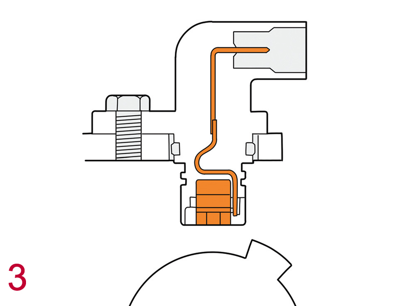
The hall sensor has an integrated circuit which is located between the rotor, and a permanent magnet that provides a magnetic field vertical to the hall element (Fig.3).
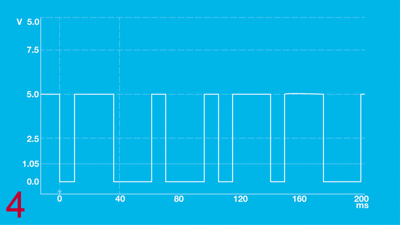
When the trigger wheel passes the sensor’s live element, the current alters the magnetic field vertical to the hall element. This gives rise to a voltage signal that is independent of the relative speed between the sensor and the trigger wheel. The integrated electronics in the hall sensor process the signal and emit it as an amplified square-wave signal (Fig.4).
With the demands of the internal combustion engine to meet performance and emissions levels, the use of these sensors has evolved. They are used to calculate injection time and duration, ignition camshaft adjustment and misfire detection. They are also used to identify the exact position of the crankshaft to the camshaft for the use of stop start systems. The current generation of rotation sensors can measure the rotational direction.
Range overview
febi supply a range of over 290 cam and crankshaft sensors, including inductive sensor and hall effect sensors. All parts are tested and verified in-house and manufactured to meet or exceed OE standards to provide highquality and optimum performance.
Other benefits are said to include a robust construction to deal with environmental influences, accuracy for fit and repair, tested according to quality standards and meeting or exceeding vehicle manufacturers’ requirements.