Hella Gutmann Solutions (HGS) investigates a case where a VW Passat is presenting exhaust gas temperature sensor error codes.
System overview
Depending on the vehicle’s features, up to four exhaust gas temperature sensors can be installed and the ECU monitors the temperature before the catalytic converter, turbocharger and also upstream and downstream of the diesel particulate filter (Fig 1).
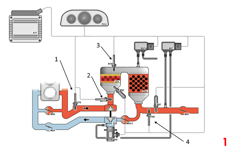
2. Exhaust gas temperature sensor in front of the cataytic converter
3. Exhaust gas temperature sensor in front of the soot particulate filter
4. Exhaust gas temperature sensor after the soot particulate filter
In vehicles without a SCR (selective catalytic reduction) catalytic converter, the exhaust gas temperature sensor behind the diesel particulate filter is not required. In the event of a defective exhaust gas temperature sensor, or in the case of implausible output values, the system switches to emergency operation or alternatively uses a substitute value to protect the relevant components from overheating. An error entry is then recorded in the ECU and the warning lamp in the dashboard is activated.
Testing with a diagnostic tool
The function of the exhaust gas temperature sensor is monitored by the respective higher level system control unit. Any errors that occur are stored in the error memory of the ECU and can be replaced by using a suitable diagnostic tool, such as a HGS mega macs device. Depending on the system, additional parameters can be displayed and used for troubleshooting.
Error code
In this function the error codes stored in the error memory can be read out and deleted. In addition, information on the error code can be called up. In this case study, the error codes 15709 and 5257 are displayed, which indicate a fault in exhaust gas temperature sensor three.
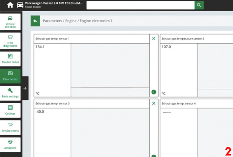
Parameters
In this function, the current measured values of the sensor in the ECU can be displayed and evaluated. Fig 2 shows a vehicle with three exhaust gas temperature sensors, with sensor three displaying a value of -40 degrees, which may be due to an interruption in the electrical wiring or to a defect in the sensor.
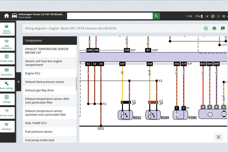
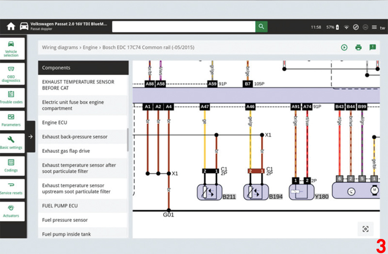
Circuit diagrams
System specific circuit diagrams can be taken from vehicle information and used for troubleshooting purposes. With this example, the PIN assignment on the exhaust gas temperature sensor or the cable colours can be read and used for further tests (Fig 3).
Maintenance and repair instructions
As part of troubleshooting, a visual inspection of the components and peripherals in the engine compartment should be carried out after the ECU diagnosis, and the sensor should be replaced if the connecting cable or sensor housing is damaged.
If the threads of the exhaust gas temperature sensors are coated, they must not be treated with an extra coating of hot thread paste and they must be tightened to the torque value specified by the vehicle manufacturer. As a guide, for a HELLA exhaust gas temperature sensor, a torque of 40 to 45Nm is recommended. However, please also observe the respective maintenance and repair instructions provided by each individual vehicle manufacturer.
Important!
The various diagnostic options in this example have been illustrated using an HGS mega macs 77 diagnostic tools. The respective test depth and variety of functions can be set out differently depending on the vehicle manufacturer and is dependent on the relevant system configuration of the ECU.

![Bosch’s ESI[tronic] diagnostic software](https://pmmonline.co.uk/wp-content/uploads/2026/03/Febi-diagnostics-tool-165x109.jpg)