OESAA, as well as members Bosch, Varta and Banner, return to take a look at Dual Mass Flywheels (DMF) and how incorrect cranking speed can have an effect on this part.
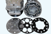
Dual Mass Flywheels (DMF) have been around since 1985 and are still a mystery to many.
All vehicle manufacturers use them and the two biggest OE suppliers LUK and Sachs have produced more than 170 million of them. They are designed to absorb vibration produced by today’s high power high compression engines improving refinement and helping to reduce emissions and yet despite excellent quality standards at both manufacturers they still on occasion fail or wear out prematurely.
Most causes of wear or noise in DMF are fairly easy to understand. DMF’s absorb vibration, if you increase the engine torsional vibration you can either induce noise or wear it out quicker.
However, the fact it absorbs vibration in many cases hides or masks that you have an engine running problem in the first place until it’s too late.
Running issues like uneven compression, injector problems or engine misfires are all common causes of DMF wear or noise and some will be covered in a later article but a lesser-known issue, which we will explore here, is incorrect cranking speed.
The DMF springs and damping will be tuned to minimise movement of the secondary mass at that cranking speed to overcome compression and the first firing. Introduce a problem which causes a slower cranking speed and it doesn’t take long for the DMF springs and damper to be working overtime causing excessive wear or a rattling DMF.
If you are presented with a car that has a noisy DMF it’s important to diagnose the cause, as simply changing the DMF may not fix the problem. If you suspect the cranking speed is slow or uneven a logical process of investigation is necessary, starting with the easy and accessible things first.
Note: the following guidance is equally relevant for vehicles with slow cranking issues without DMF, also in the event of a non-crank situation then other relevant tests will be required. Bosch advises that the following tests relate to conventional starter systems. The latest developments using combined alternator/starter systems will require additional manufacturer specific tests in conjunction with suitable diagnostic equipment and information.

The Battery
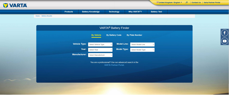
Banner and Varta advise not to ignore the obvious, is it the correct specification battery for the application? Both OE battery suppliers have excellent online battery finders so check the capacity (CCA and AH) and the battery technology (Flooded or AGM/EFB for Stop-Start vehicles). Fitting an AGM/EFB to a standard vehicle could be described as an ‘upgrade’ and may work well, however, fitting a standard flooded battery to a Stop-Start vehicle will very much have a shortened lifespan. The charging system of Stop-Start is designed to very quickly replenish the battery and uses voltages and currents that the standard battery cannot accept long-term, be aware also that replacing a battery in a Stop-Start car often requires the relevant ECU (Engine ECU, Charging ECU or BCM etc) to be re-set to calibrate the charge curve and also inform the ECU of any change to specification, for example 74AH instead of 70.
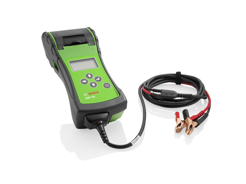
Check the battery terminals themselves then check the voltage using a multi meter, preferably in conjunction with a battery tester like the Bosch BAT131.
Check the static/resting voltage first, if it’s below 12.5v it is technically a flat battery and will need charging. It should be 12.7-12.8v for normal lead acid or approximately 12.9v for AGM/EFB. Note: that if a battery has just been charged or the engine has just been running then a surface charge may be present which increases the voltage slightly, switching on the headlamps for 30 seconds will scrub this off and help make the measurements more accurate.
With regards to charging a standard lead-acid (flooded) battery a guide would be that a 60AH unit would be charged at 6 Amps and may take up to 10 hours to charge fully.
Modern Gel, AGM/EFB or Li batteries are different technologies and to correctly/fully recharge these requires the use of Microprocessor Controlled chargers, which carefully sense and regulate both current and voltage to avoid overcharging and irreparable damage.
With the correct specification battery in place, fully charged and tested, known-good or replaced, you can continue with your checks but remember you should also confirm it is being charged correctly by the vehicle itself – referring to correct manufacturers procedures and specifications.
Using your voltmeter, now check the battery under load while the starter is engaged, generally use 9.6v as a minimum or lowest figure – this is recorded at the initial point of cranking as the starter attempts to turn the dormant/standing engine.
More advanced meters have a max/min record function which helps make this more accurate and easier to catch, but using an oscilloscope like the Bosch FSA is the ‘Gold Standard’ test here, due to its sampling rate and its ability to display on screen – 8.0v is regarded as minimum for a scope test.
Once the engine is rotating, the battery will generally show a higher figure of circa 10.5v due to reduced load of merely maintaining turning compared to initially starting to turn dead mass. A good way to imagine this is thinking of the effort required to start pushing a stationary car compared to keeping it going once actually moving.
Cranking/Starter Motor
If the cranking speed is still slower than specified, we need to consider the possible root causes:
- Mechanical friction fault/partially seized component for example engine internal shafts/bearings or engine external components like exhaust/vacuum pump, alternator or aux pulley/bearing etc.
- An electrical issue for example faulty starter motor, wiring/connections etc.
The most common causes of slow crank concerns are related to the battery or the actual starter motor and its power supply circuits/connections, so we will concentrate on this possibility.
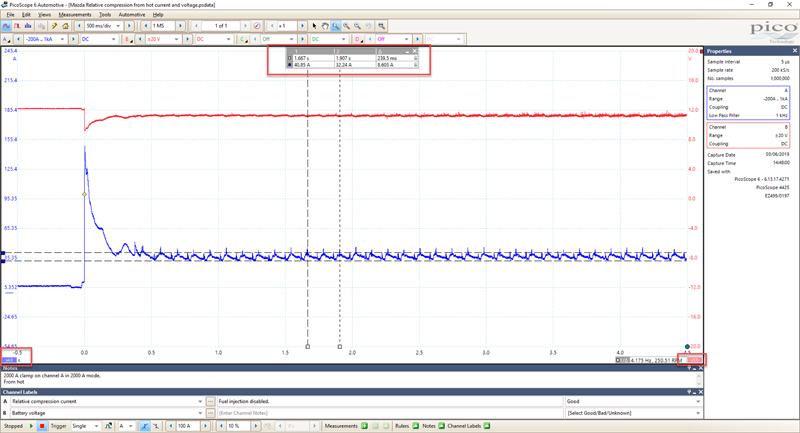
A voltmeter on the battery and a current clamp fixed around the starter cable can display the information required. However, an oscilloscope simultaneously measuring both voltage and current is an invaluable tool for these tests and can easily prove not only the battery’s supply potential but can also show the current draw and the actual engine cranking speed. This is made even easier as a scope displays a ’footprint’, which can be stored and analysed in great detail.
If the tests indicate that the battery potential is good and the current test shows that the current draw is higher than specified, this generally indicates that the external wiring and connections are good. This is working on the principal that the starter would not be able to draw a high current/demand through a bad connection or corroded/damaged wire. In this case we can now use the scope current trace to further view items like initial current draw, which often indicates worn starter pinion bush. This allows us to observe the current flow as the cylinders go over compression, also finding the exact rotational speed.
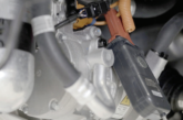
Aside from an engine mechanical restriction as mentioned above, a very high initial current draw added to high cranking current is generally caused by a faulty starter motor. Remember: Always test against specification and remember to factor-in influences like thicker oil and lower battery voltage during a weather cold snap, for example, which will affect all readings. Bosch also reminded us that swarf found around the magnetic starter motor may have come from the DMF so if found, both will need to be replaced.
Voltage-Drop tests
If the current and voltage draw is lower than specified/anticipated and/or possibly erratic, then so-called voltage-drop tests are the next step, which can also be used as a belt and braces approach to confirm a suspect/faulty component.
Several voltage tests are made at various points in the circuit while the circuit is under load. In this case as the starter attempts to turn the engine and where a restriction is present which means there will be a voltage change.
There are approximately eight tests that could actually be carried out on a starter circuit, but seasoned Technician’s can reduce this to four or less depending on the fault.
For a simple example, using a voltmeter or the scope, measure from the battery positive post to the battery negative post – the actual post not the terminal connected to the wires. Then, crank the engine and note the reading, now change the test leads to the actual terminals connected to the wires and note the reading. Any difference in voltage is due to poor connections between the actual post and the terminal. Ideally, if the connections are clean there will be no difference, but if the terminals are dirty/insecure then voltage will be lost. Further testing between each individual post and terminal can then identify the exact cause but remember this must always be done under load.
Measure between the battery positive post and the actual starter positive post or threads of the starter main power supply line connection – not the starter wiring terminal or the securing nut. There should generally be no more than 0.3v (300mv) shown on the meter if, however, there is say 2v shown, this indicates that power is being lost as there is a 2v drop from point to point. This will, in turn, prevent the starter from turning over correctly due to the reduced power supply and energy flow.
Note: If measuring directly from the battery post to the starter post gets less than 0.3v, we have confirmed every connection between the battery and the starter on that particular circuit, so that test is complete. However, if we measured say 1 or 2v here, then we would need to change the meter lead at the starter post to say the starter feed wire terminal and so on to prove where the voltage is being lost, for example a bad terminal connection at the starter, securing nut loose, bad wiring etc.
Further tests at different points in the circuit are required to pinpoint the cause. The same tests are used on the earth circuit between the battery negative post and the starter casing, between the starter solenoid terminals and the main motor terminal etc. and in fact are the same tests used to pinpoint other electrical components like the alternator when there is a charging fault.
Note: An accepted maximum combined voltage drop on a starter circuit is generally 0.5v total, this may be a shared voltage, which when analysed may be say 0.2v on the negative side and 0.3v on the positive. Further analysis may show that 0.1v drop was between the battery positive post and the battery terminal and 0.2v drop was between the terminal at the end of the main wire and the actual starter post itself etc. Sachs recommends a thorough cleaning of any connections with a wire brush if possible prior to refitting and retightening to the correct torque and to extend the life of your repair. Don’t forget to protect the connection from corrosion.
Using the above tests we can quickly confirm the causes of a slow cranking engine.
The oscilloscope trace also displays a relative compression test which, in turn, may show a possible mechanical issue that requires further investigation. This could be, for example, a low cylinder compression which is another source of trouble for the DMF’s longevity as the constantly changing cranking speed, where say three cylinders have good compression and one has poor compression so is easier to turn, added to doubtlessly erratic or less-smooth engine idle, provides additional stresses for it to attempt to absorb and will vastly shorten its lifespan.