PMM’s hot-wired fixer Ben Johnson has his dreams of exacting a full and comprehensive repair scuppered once again by a member of the Finnish BMW-owning public.
After another week of repairing yet again ad-infinitum what must be the most unreliable BMW product ever made – the F15 X5 – it was quite a refreshing change to be handed a job card for something other than these troublesome vehicles. The patient this week? A rather hot and bothered F25, colloquially known as the X3. This high miler, equipped with the trusty N47 engine, was reported to have some cooling fan issues. That was about as much info as I could glean from the job card, as per usual.
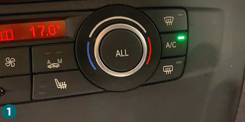
First off, a quick test: I hit the A/C button which, assuming there was sufficient refrigerant, would demand a bit more from the fan than its currently adopted dead seagull pose (Fig.1).
Yes, the fan – sulking like an insolent school child – was refusing to do anything at all except sit there like a big useless lump of sharp, finger-shredding plastic.
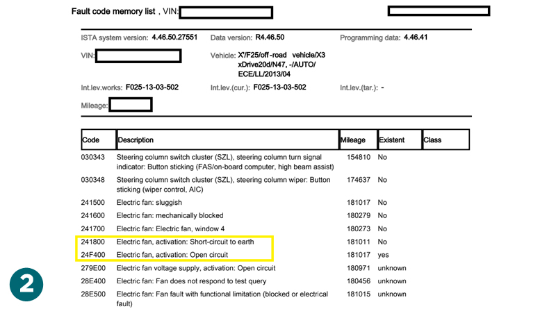
A quick check of the fault codes revealed something a bit more tantalising than the usual simple LIN bus failure codes. As many of you reading this will know that often, these result nine times out of 10 in a straightforward LIN transceiver failure within the cooling fan electronics – a quick fan replacement and Bob’s your uncle. But not this time. No – this fault was new to me. Interesting. The first thing that caught my eye in the fault code list was the pair of troublemakers: 241800 and 24F400 (Fig.2). These codes suggested an issue along the line or a series of unfortunate events preventing the output of a ground on this line. At the time, I wasn’t quite sure if I was dealing with a wiring fault, a relay fault, or even the DDE itself. The ground is output from the DDE and then routed to a standard 4-pin relay which, when energised, supplies power to the fan unit. Incidentally, the relay is easy to test. You can use a 9V battery across the coil and listen for the satisfying click, or use a Power Probe to power it properly and see if it lights up a test lamp – you know what I mean, I don’t need to explain this to the PMM seasoned readers, do I? Needless to say, I gave the relay a quick test and found it was in perfect running order.
Now, the fan unit is nothing to write home about – it’s got a chassis ground, a LIN command line for PWM control from the DDE and a permanent live power supply. I sussed out that the easiest place to start was to check the live at the fan, and wouldn’t you know it, it was as dead as a doornail. At least I didn’t have to deal with an intermittent fault – those are a real pain in the spanners. Or did I? Let us continue on with this debacle.
Although, before I start rambling on about how I diagnosed this fault, please take a moment to familiarise yourselves with how the system works. I’ve crafted a handy diagram just for you, dear readers (Fig.3).
Wiring system
With the thick 12V power supply wire not showing anything at the fan, a quick check of the terminal 30 and terminal 86 at the fan relay showed a healthy 12V. This left only terminal 85 at the relay to check. Terminal 85 showed battery voltage even when a fan activation test was attempted by the everslow, ever-clunky BMW ISTA tester, instead of activating the fan test I received a rather angry error message in German about conditions being incorrect – brilliant, just what I needed. The question was, why do we have voltage and not a ground switch here? The relay will never switch if the coil has no ground, and the fan won’t work if the power is missing. It’s like trying to start a bonfire with a soggy matchstick.
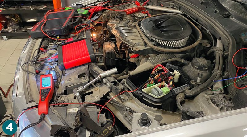
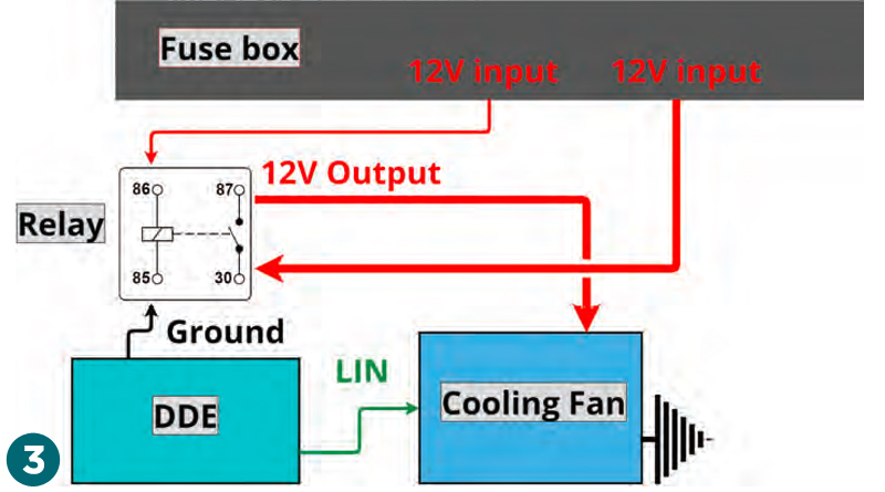
Powering up the relay was a cinch with the Power Probe Maestro. Additionally, I hooked up a handy test light onto the terminal 87 thick gauge wire at the fan unit to see if the relay was actually doing its job and transferring power to the fan (Fig.4). Since the fan wouldn’t start to spin until either the A/C was activated or I used the ISTA activation test once again, I chose the latter. This time, I was able to activate the fan within varying PWM ranges – so the fan works when the relay terminal is bypassed. That’s one mystery solved. Now, onto the next conundrum: why on earth is there 12V on the ground trigger wire? It’s like finding a chocolate teapot – completely useless and utterly confusing. The DDE on the X3 is mercifully more accessible compared to some other BMW models, only requiring the removal of a few torx screws.
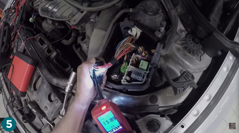
The DDE is split into two modules, and the left-side module, Module 1, houses the connector for the ground output from the DDE. I discovered that the same battery voltage was present at the DDE (Fig.5) as at the relay’s last point in the circuit, which made me dread an internal fault within the DDE. To confirm this, I simply removed the trigger wire from the DDE connector, reattached the connector minus the trigger wire, and erased the fault codes.
All clear for the DDE
Running the engine again showed a ground present at the DDE pin, which I accessed through the small hole left by the removed wire. A slimline Fluke-type probe was inserted to facilitate the measurement. So, the DDE wasn’t faulty – hurrah! – but the wire was as effective as a waterproof teabag. The next question was where and how it was faulty.
This was clearly the moment to make one of those “phone calls”. Unsurprisingly, the customer was less enthusiastic about locating the break in the wire and insisted we simply make up a new wire to bypass the faulty one. Not what I wanted, but then again, when do us mechanics ever get what we want? It’s a bit like asking for a steak and being given a tofu salad.
The best thing about modern electronics – and also the worst – is trying to explain the logic of fault detection to newcomers. Just the other day, I had this very conversation with one of the young lads I work with and I’ll replicate my explanation here for your amusement. The DDE is designed to check for shorts to protect itself, detaching from situations where a short circuit might arise. Shorts can cause fires and that would certainly ruin your day.
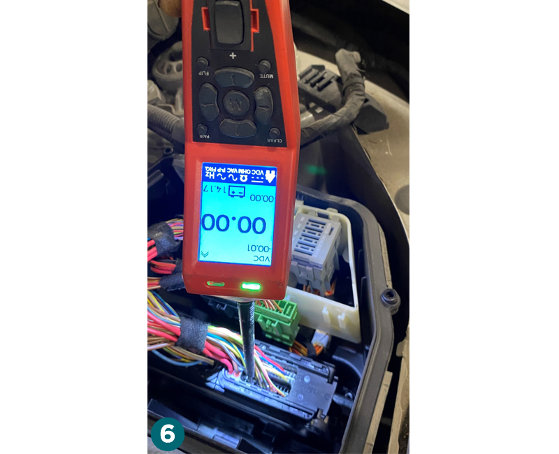
In this case, the reason the DDE didn’t go up in flames is because it detected a short and switched off the ground on the pin that sends the ground to relay terminal 85. What can occasionally happen, as it did here, is that the problem may randomly resolve itself. Wires can move, and when they shift away from the chafed area, they move away from the shorted 12V power source. The DDE recognises this and restores the line, even if only temporarily (Fig.6).
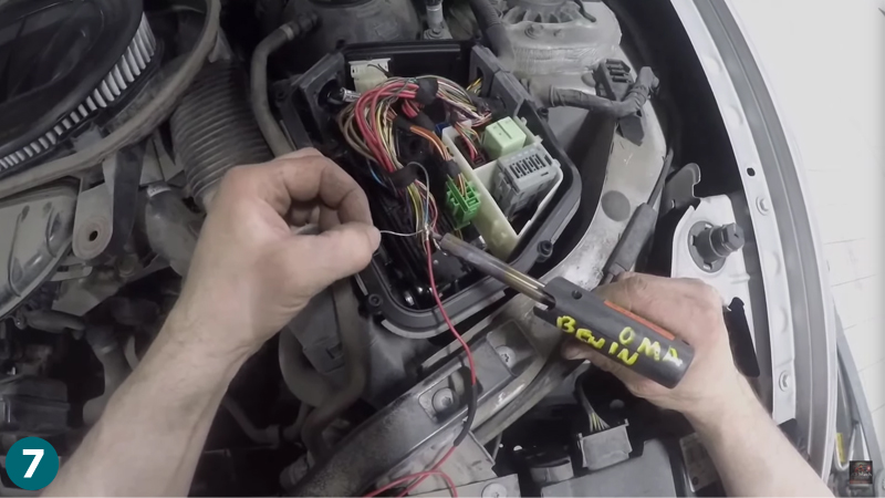
Ideally, various techniques would be employed to find the short, and often stripping back the harness is the fastest option. However, the customer opted only to pay for replacing the wire, so that’s exactly what I did. A handy 3-pin connector exists upstream of the relay, housing this infamous trigger wire. Removing it and plugging back in the connector minus the wire allowed me to solder a new wire at that point and snip it at the DDE (Fig.7). The result was a new wire, but the short area remained unidentified – a situation that always leaves a bad taste in my mouth.
I’ve preached for years that a short must be found and isolated because where one wire fails, another is ready to fail. I do what I’m paid to do and do it as well as I can. It’s a bit like being asked to build a car with a hammer and a rubber chicken – you make do with what you’ve got and hope for the best.
Time and place for oscilloscopes
To end this article, I’ll leave some advice that may be handy for newcomers to the field of automotive fault finding. I’ve spent decades observing other fault finders and honing my own skills and I’ve been meaning to impart some wisdom regarding the use of oscilloscopes for quite some time now. Many fault finders seem to find it wholly necessary to break out an oscilloscope at the drop of a hat.
Here’s a pro tip for you: if you’re dealing with a suspected component power supply, ground, or signal fault, what can you do other than measure the signals? Simple – remove the connector, erase the fault codes and see what comes back. If you have new fault codes relating to removed wires or connectors that you didn’t have previously, then clearly the receiving control unit is recognising this and setting a new DTC. Do you need to continue to check the wiring or break out the scope? This isn’t an exact science, but in most cases, it’s sufficient to help assess the state of play in a circuit. Scoping is good but there is a time and place for it.


