Steve Smith, from Pico Technology, provides some useful advice for carrying out diagnostics on a Toyota Auris hybrid.
It goes without saying that hybrid and electric vehicles (EVs) should be treated with caution when it comes to service, repair, and of course, diagnostics. This comes as no surprise and, while the same applies to any vehicle, with EVs and hybrids there are added dangers. We should not be fearful of such technology as long as we understand the safety procedures involved and the operation of the system we wish to diagnose.
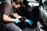
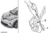
Here is one such case where a Toyota Auris hybrid arrived with the hybrid warning light illuminated. The vehicle had been converted for covert surveillance with sensitive recording devices spread throughout the cabin.
Trying not to be fazed by what lies beneath and keeping an eye on the ball, the fault code P0A82-123 was extracted from the Hybrid Control Unit (HCU). Hybrid codes include what are known as INF (information) codes and in this case we had P0A82 as our DTC and 123 as our INF code.
The INF code provides a thorough and specific overview of hybrid component operation prior to, during and after the point of DTC detection, so it assists technicians with historical facts to support a conclusive diagnosis. Access to an OEM scan tool allowed for interpretation of the INF code to reveal ‘occurrence order 1’.
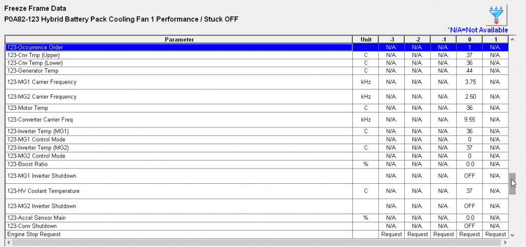
This indicated P0A82 was the initial code that illuminated the hybrid warning light, and provided immense value where multiple fault codes are stored.
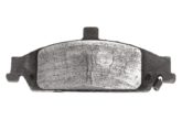
The DTC P0A82 referred to a ‘Hybrid Battery Cooling Fan Performance error’.
A description of the system and fault code indicated a problem with the cooling fan control circuit responsible for cooling the high voltage (HV) battery. Understanding the operation of the system is essential when diagnosing recorded faults. After all, how can we diagnose components if we don’t know how they function?
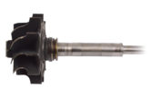
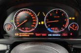
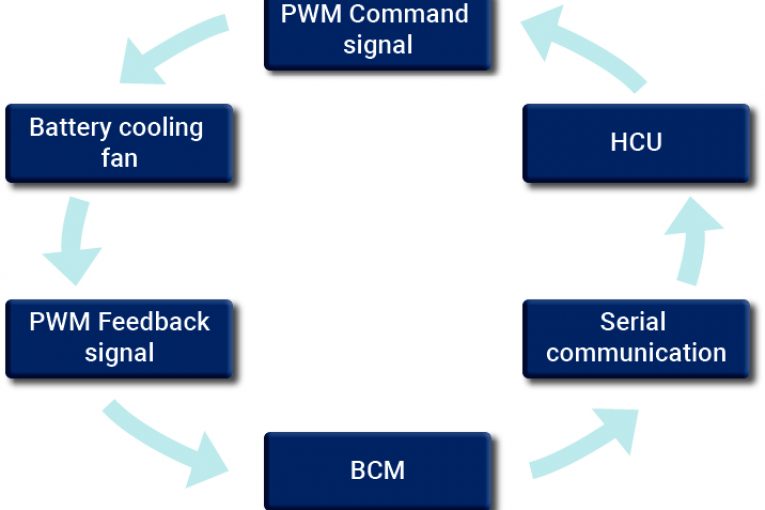
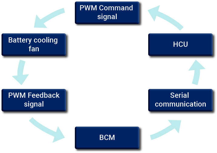
The speed of the battery cooling fan is controlled in a loop fashion by the HCU. A command signal from the HCU is delivered to the cooling fan to increase or decrease fan speed, depending on battery temperature. A feedback signal from the cooling fan is sent to the Battery Control Module (BCM), where this value is converted into serial data and returned to the HCU, completing the loop. An initial inspection revealed the cooling fan to be running continuously at high speed, which had been difficult to detect amongst the surveillance equipment.
In order to access all the relevant components for circuit evaluation, the hybrid system is required to be shutdown using the following procedure:
1. Ignition off and key secured at least 2m away from the vehicle
2. 12V battery negative terminal disconnected
3. Signage placed about the vehicle indicating ‘Caution, HV testing in progress’
4. Approved safety gloves checked for leakage and worn, prior to Step 5
5. HV Service Plug (Isolator) removed from HV battery pack and secured away from vehicle
6. Wait 10 minutes for HV capacitors to discharge
7. With safety gloves on, remove the invertor cover (engine bay) and measure all HV terminals for the presence of any voltage (AC and DC) using the appropriate HV tester or HV probe with PicoScope Note: No voltage should be present at any HV terminal under the invertor cover
8. Refit the invertor cover
9. The HV system is now shut down and it is safe to continue with diagnosis
Access to the BCM is via the HV battery cover, so it is mildly intrusive into the heart of the HV system. At this point there was no need to feel uncomfortable as the HV system was shut down as above.
Testing the cooling fan circuit required the 12V battery to be reconnected and the ignition switched on, with the hybrid system still isolated. This is normal procedure and generated additional DTCs, (these were erased on completion of the repair). Note: Switching the ignition on with the HV service plug removed does not activate the HV system.
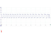
With the ignition on, PicoScope was connected to the command and feedback signals (CH A and B) along with the serial communication signal (CH C and D) within the cooling fan circuit. Immediately we could see the command signal fixed at 0V instead of the required PWM signal.
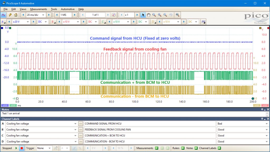
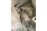
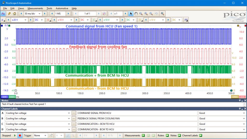
A continuity test of the command signal wire revealed a short circuit to chassis ground at one of the surveillance camera mounting bolts, resulting in a default max fan speed to ensure sufficient HV battery cooling. With the short circuit repaired, full closed loop control of the battery cooling fan was restored and confirmed using the component test function of the scan tool.
To conclude:
We shouldn’t be alarmed by HV systems; there are dangers with all vehicles regardless of their power source. Safety is always paramount, so ensure your safety training is up-to-date, follow repair manual procedures, understand the operation of the system under test and document your results during diagnosis.