At some point vehicles fitted with electric parking brakes will have to go through an MOT test. Normally, the tester will test a conventional parking brake on a roller brake tester by applying the brake lever and observing the individual and total brake force; and the balance between left and right. This requires the brake to be applied in a controlled and progressive manner.
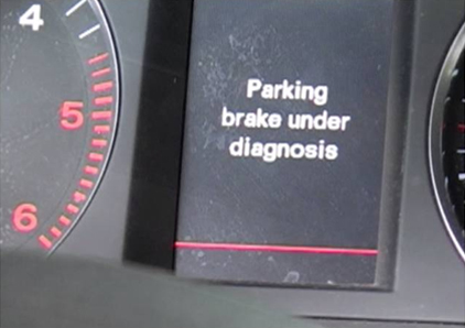
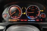
Normal application of the electric parking brake does not need to have this subtlety. The programmers have built into the software, an inspection mode which is detected by the EPB ECU when the front wheels are at rest and the rear wheels have been turning for 5 or more seconds at a steady rate between 2.5km/h and 9km/h. A warning light or message informs the tester that the vehicle is in inspection mode and the brake button can be pressed four times in succession to gradually increase the braking force to maximum.
Please note that the process may differ from vehicle to vehicle. Always refer to the tester’s manual!
Brake servicing
Electric parking brake systems are active even when the ignition is off. Integral systems actively adjust the brakes to account for brake pad shrinkage as the system cools – if the parking brake is not applied over a distance of 1,000km, brake pad adjustment is carried out automatically, meaning care has to be taken when working on the system.
The cable pull systems use conventional braking components and require little in changes to servicing procedures. The EPB actuator should be disabled and this can be done by either your scan tool or by procedures detailed in the workshop manual.

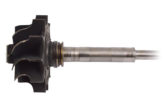
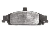
The integral systems use a motor wound thrust nut which pushes the calliper piston and thus compensates for brake pad wear. To change the brake pads the thrust nut will have to be fully wound back through the use of a scan tool with the correct software or a dedicated EPB service tool. Once the thrust nut is wound back the calliper piston can be forced back into the calliper using the normal service tool before the brake is serviced in the conventional way.
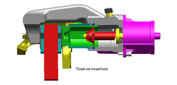
On completion the scan tool is used to wind the thrust nut forward to adjust the brake, however the process may bring up digital trouble codes (DTCs) which will have to be cleared.
Great inconvenience is caused when the system fails with the parking brake applied, usually due to control button failure or electrical failure. The scan tool will allow the technician to control the brake but in the absence of the correct equipment or, in the case of a communication/electrical system failure, there are other strategies.
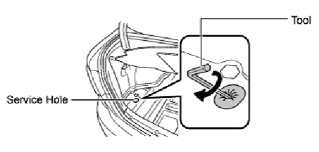
Most of the cable-pull systems have a release mechanism. One system involves winding the motor back through an access hole in the boot. A special tool, supplied with the vehicle is used to turn the electric motor remotely – a process that can involve 300 turns and take up to 20 minutes if done by hand!
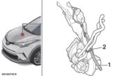
Other systems use a ripcord. Incorporating a ratchet and pawl system into the cable adjuster, a separate cable is actuated from a lever in the glove compartment. There are obvious hazards when releasing an electric parking brake manually so follow the safety instructions provided, but to put it simply make sure the vehicle cannot roll away.
The integral system presents a different problem in that there is no obvious manual override. This system uses a conventional DC motor, which can be operated by an external power supply, however great care must be taken if damage to the system is to be prevented. Under normal operation the motor current varies between 2-5A when winding and up to 17A when stalled. Prolonged application of an external power supply when the motor is stalled, will quickly burn it out. The direction of motor travel is reversed when the polarity is reversed and the motor can be heard to operate.
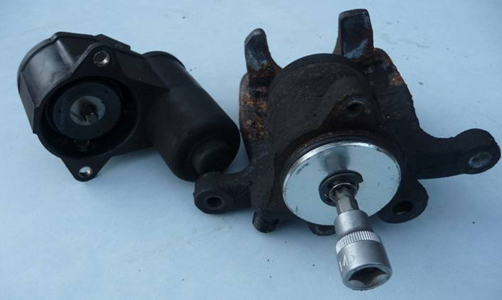
A second option is to manually wind the drive nut. This is done by removing the motor unit to gain access to the spindle drive which is in the form of a spline or torx (depending on the model). Turning the drive in a clockwise direction winds the drive nut back into the unit, releasing the force on the pads.
Diagnosis
Operation of the brake unit of either type of EPB is audible and changes in its operation may be heard. As always, information from the driver about their experience is an essential part of the diagnostic process.
Scan tool diagnostics will give information about malfunction and operation outside normal parameters, resulting in the production of fault codes. Save or record any fault codes before erasing them and then run the system through normal operation to identify the most prevalent codes.
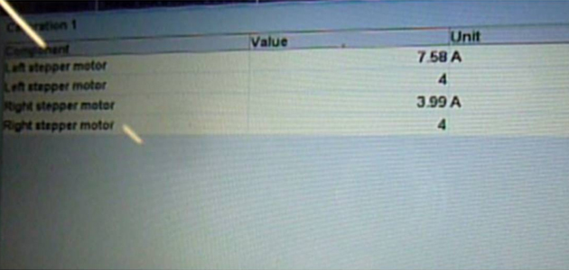
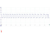
Current data can be observed and parameters include: the condition of the brake switch, clutch sensor, longitudinal accelerometer and the current draw on the actuator motors. Active testing can be carried out using the scan tool and the current draw observed; this type of testing also allows the technician to check for voltages at the harness connectors whilst they are disconnected.
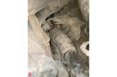
Cable pull systems are at the mercy of good brake hub maintenance. Problems within the calliper brake or drum brake mechanism can show up as fault codes in the EPB system.
Integral systems have fewer moving parts and do not suffer from the problems associated with cables. Excessive current draw will usually be caused by restriction to piston movement. Like all disc brake systems, pad-to-disc clearance relies upon flexing of the piston seal, so brake drag is a fair indication of restricted movement of the calliper piston.
In conclusion
These systems offer a great deal of freedom for the driver and, because of their relative simplicity, do not challenge the technician any more than they need to.
Many thanks to TRW for the use of their images and to John Sherwin of Somercotes, Derbyshire for their invaluable assistance.
After more technical information? To read Part 1 of this series click here
To read Part 2 of this series click here