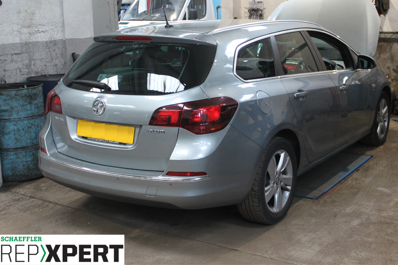
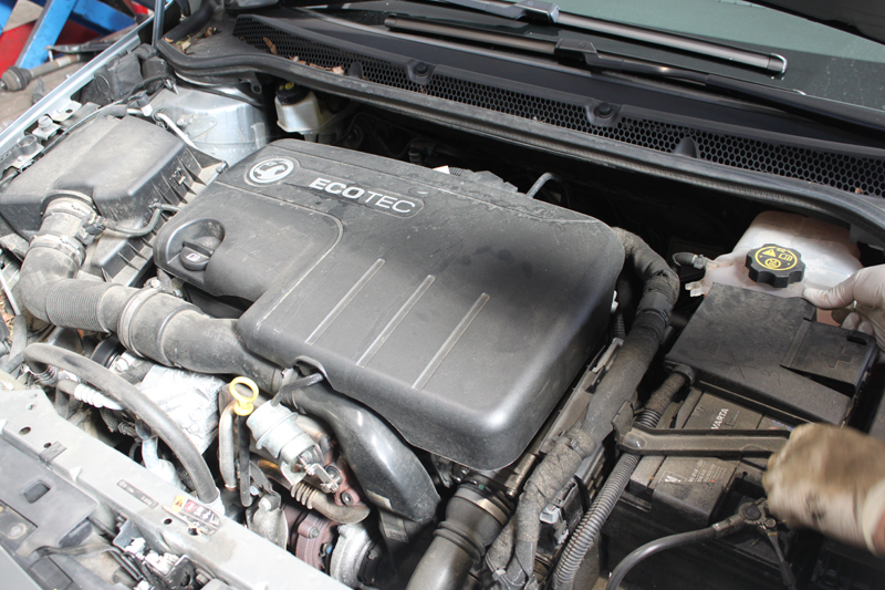
REPXPERT’s Alistair Mason replaced the clutch and flywheel on a Vauxhall Astra 1.7L CDTI, which had racked up more than 91,000 miles. After complaints that the vehicle’s clutch was ‘slipping’, a short road test confirmed that it needed to be replaced.
Step-by-step procedure
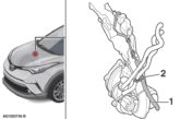
Firstly, with the vehicle positioned on the ramp, remove the steering column-to-steering rack pinch bolt, which is located in the driver’s footwell and disconnect the steering column from the rack.
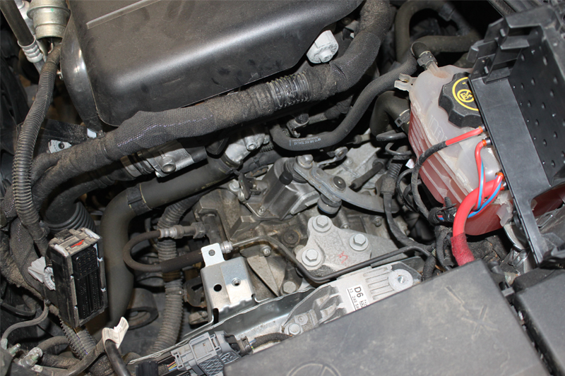
Open the bonnet, disconnect the battery terminals (see below) and remove the battery. Remove the ECU, clipped to the side of the battery carrier, and unclip the wiring loom from the battery carrier before taking it away.
These steps now allow good access to the top of the gearbox (see below).
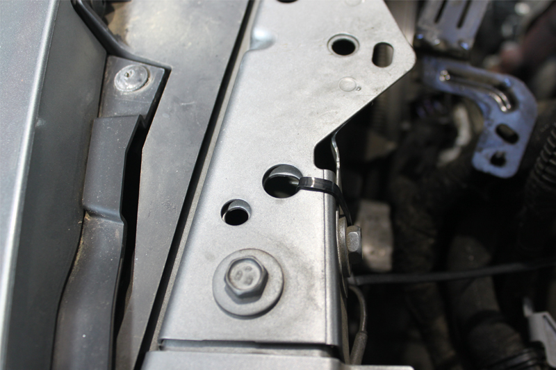
Clamp the flexible part of the hydraulic clutch pipe and then detach the pipe from the concentric slave cylinder (CSC) by releasing the clip. Remove the gear cables from the linkage by levering off and then stow them in the bulkhead area. At this point, hold the coolant radiator in position by attaching two cable ties through the radiator and fixing them to the slam panel (see below), which prevents the radiator moving when the front subframe is lowered.
There is an ABS wiring loom attached to the ABS unit, which needs to be unclipped to allow some additional free play on the loom when the subframe is lowered. Unscrew the retaining nuts that hold the engine wiring loom bracket to the top of the bell housing, remove the small bracket by the CSC and then remove the top bell housing bolts.
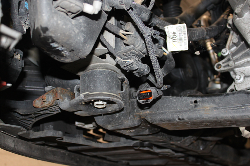
Raise the vehicle lift to gain access to the underside and remove the engine undertray, lower the vehicle lift to waist height and remove the N/S/F wheel and the wheel arch liner. Detach the N/S/F anti-roll bar link from the suspension strut and unclip the ABS wiring loom from the front subframe and disconnect the multiplug at the N/S/F corner of the sub frame (see below).
The ABS wiring loom also needs to be unclipped from the front subframe on the O/S to allow the subframe to be lowered.
Next, place an oil drainer underneath the gearbox and drain the gearbox oil. Whilst the oil is draining, remove the exhaust mounting, the subframe supports from the rear, the rear gearbox mounting and the bolts for the front gearbox mounting – the mounting will stay attached to the subframe during this repair.
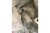
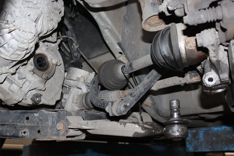
At this point, the gearbox oil drain plug can be refitted and torqued to the manufacturer’s specification. The N/S/F bottom ball joint pinch bolt can now be detached. Now uninstall the bottom arm from the hub assembly and pull the hub assembly out, drawing the driveshaft out of the gearbox. This job may require some leverage, as the driveshaft is retained with a snap ring, but once removed from the gearbox, it can be secured close to the bulkhead area (see below).
Now support the engine using either an engine brace or a second transmission jack and unscrew the front subframe bolts located at the front and rear of the subframe. The front of it will then lower sufficiently to give enough clearance to remove the gearbox. With the engine supported, the top gearbox mounting needs to be taken away from the engine bay.
Once removed, lower the engine and gearbox slightly to aid the removal of the gearbox. Support it by using a transmission jack and unscrew the final bell housing bolts, noting their designation, before easing the gearbox away from the engine.
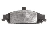
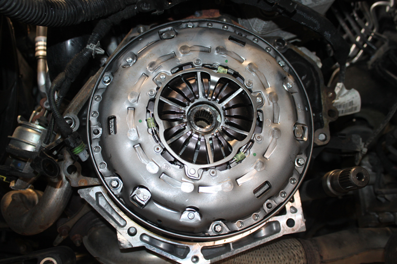
During this particular replacement, it was evident that the clutch had reached the end of its service life, as the three small yellow springs on the self-adjusting clutch mechanism had fully extended, indicating it was fully-adjusted.
Replacing the flywheel
Remove the clutch assembly from the flywheel by undoing the six bolts, and ease the clutch assembly off the dual mass flywheel (DMF). Check for any leaks from the engine, either oil or coolant, which could contaminate the new flywheel and clutch assembly, and rectify if required. Now remove any clutch dust from the engine using brake and clutch dust cleaner before mounting the new flywheel, as this could contaminate the new components. Ensure the new flywheel is correct by comparing dimensions and the ring gear teeth. Mount the new DMF, guaranteeing any alignment dowels are correctly positioned, and secure into place using new flywheel bolts. Tighten them evenly and sequentially, before torqueing them to the manufacturer’s specification.
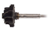
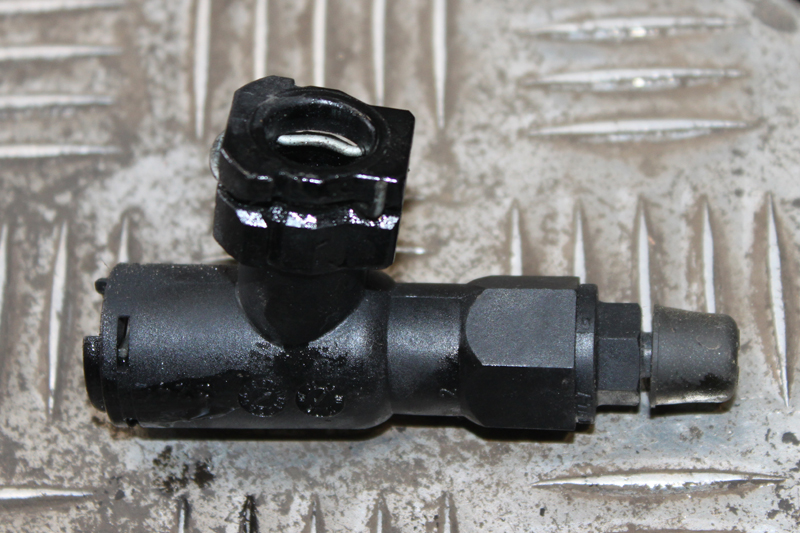
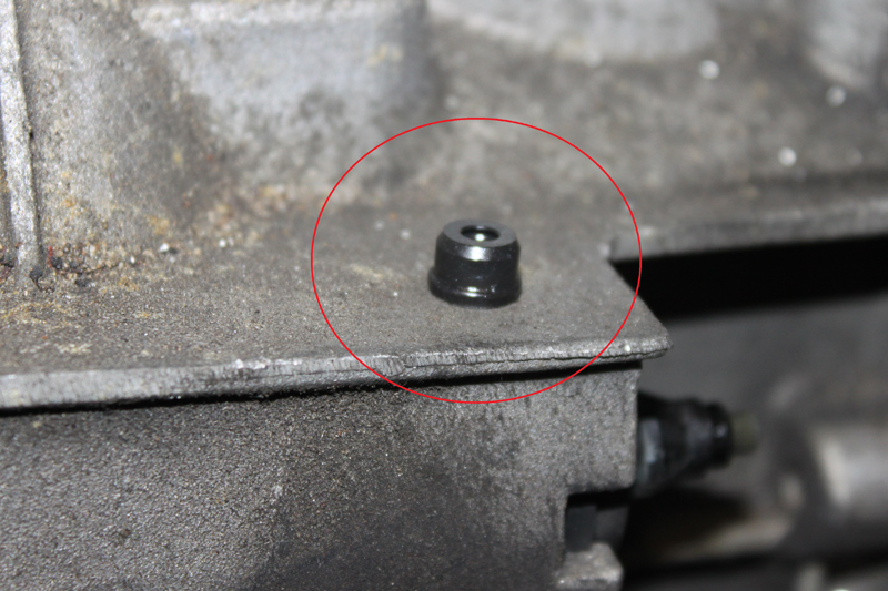
Now remove the CSC from the bell housing on the gearbox, with the first step being to remove the black plastic connector from the gearbox, achieved by releasing the small spring retaining clip and then easing it away from the gearbox (see below).
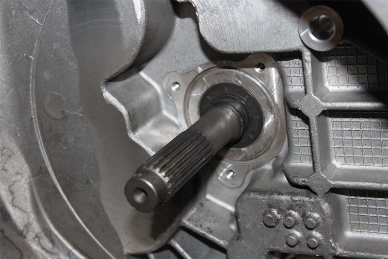
Remove the black plastic bush that positions the CSC pipe as it passes through the bell housing, and then the three retaining bolts from the CSC. Finally, detach the CSC from the input shaft and gearbox. At this point, check there are no oil leaks from the input shaft oil seal (see below). If there are, rectify the leak and clean the bell housing using brake and clutch dust cleaner.
Once complete, mount the new CSC, ensuring that it is mounted squarely, before tightening and torqueing the bolts. Refit the black plastic location bush onto the pipe and position it in the bell housing.
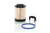
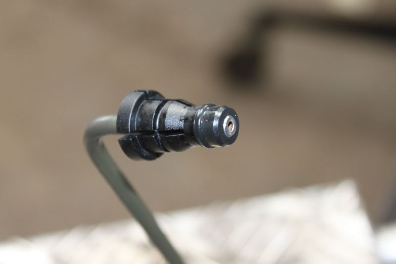
An area to pay special attention to is the black pipe connector, attached to the new CSC pipe, as there is a small rubber seal that is in the shape of a top hat. This must be removed from the old pipe (see below). If it is not present on the old pipe, it may still be located in the connector. It must be found and discarded, as the new CSC pipe comes with a new seal. Apply a light smear of brake fluid and ease the connector into position until the spring clip locates correctly.
Lightly smear some high melting point grease on the gearbox input shaft, then place the new clutch plate onto the input shaft, moving it back and forth a couple of times, which will achieve two things: evenly distributing the grease on the input shaft and ensuring the clutch plate splines are of the correct fitment. Next, remove the clutch plate and wipe off any excess grease.
Fitting the new clutch
Now fit the new clutch to the DMF. Firstly, ensure the clutch plate is fitted the correct way with either ‘Gearbox Side’ or ‘Getriebe Seite’ stamped on the centre of the clutch plate facing the gearbox. Then use a clutch alignment tool to align the clutch plate centrally. With the clutch mounted correctly, install the clutch bolts, tighten and torque evenly and sequentially (see below).
Before reinstalling the gearbox, flush out the old clutch fluid, which may be contaminated from the system, by simply draining it into a waste container and replenishing it with new clean clutch fluid. Whilst it is draining, pour clean fluid into the reservoir, and when the new fluid is flowing through the system, clamp the hose. Once finished, the gearbox is ready for installation. Check that the gearbox alignment dowels are installed correctly in the engine block and that the spacer plate is aligned correctly.
Lift the gearbox into position over the subframe and support it with the transmission jack, ensuring the gearbox is positioned correctly on the jack so it will align correctly with the engine as it is eased into position. When in position, secure it using an accessible bell housing bolt.
Reassemble in reverse order of removal, remembering to refill the gearbox with the correct quantity and specification of oil, and torque all bolts to the manufacturer’s specification. Bleed the clutch –‘gravity- bleeding’ worked well on this occasion, but there are other reliable methods, such as vacuum bleeding or the two-man process of manual bleeding.
When assembly is complete, reset all electrical consumers, as the battery has been disconnected, and carry out a full road test to ensure a complete and successful repair.