Blue Print Technical Consultant, Jim Gilmour, looks at the Denso HP2 fuel system, the way in which it operates and the common problems associated with it.
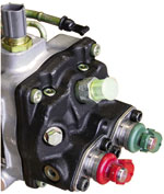
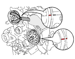
This particular system was fitted to Toyota, Nissan, Renault, Vauxhall/Opel and Isuzu vehicles from around 1999 to 2007, but may vary from model to model. The HP2 system is easily identifiable because it uses two Suction Control Valves. Looking on the back of the pump you will see there are two electrically operated solenoids – one red and one green (see image right).
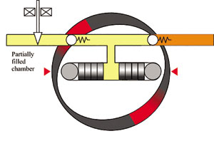
Why two? Well the system is not like any other. The job of the SCV is to control the flow of fuel oil to the pumping chamber of the high pressure pump, as a means of controlling the pressure in the common rail. The pumping chamber in other systems (including Bosch, Siemens and Denso HP3), consists of a cam, piston and powerful spring. The spring provides the inlet stroke and the cam provides the outlet stroke; this means that the engine has to provide a large amount of power to operate the pump. The Denso HP2 system uses a single internal eccentric cam and two pumping chambers.
The two pumping chamber’s pistons are set at 90° to each other so that they’re on opposite strokes, but are operated by the same cam. In the image below Chamber 2 is on the intake stroke; fuel from the internal feed pump enters the chamber via the check valve when the SCV is open and forces the pistons apart. The amount of fuel entering the chamber is controlled by how long the SCV is open during the intake stroke. A short opening time will only partially fill the chamber, by moving the pistons out a reduced amount so that the rollers do not touch the cam. This means the cam has to turn until the rollers touch the cam and start the outlet stroke.
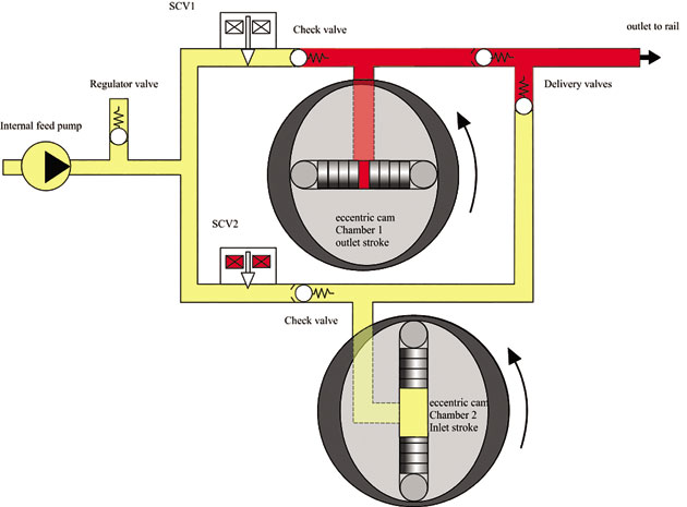
This diagram shows a schematic of the system
The amount of fuel delivered to the common rail is a function of the angle through which the rollers are in contact with the cam (shaded red below. Both the contact angle and the common rail pressure are parameters on your scan tool; the relationship between engine speed, contact angle, injection quantity and common rail pressure are monitored for plausibility.
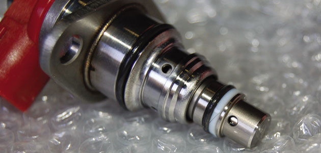
The single pumping chamber
Pump timing
Unlike the SCVs in other systems (where the opening of the valve is controlled in degrees by using Pulse Width Modulation), the Denso HP2 system uses a timed open period. The result of this is less effort required to operate the pump. As a result of this method of control, the opening of the SCV has to be timed to allow the flow of fuel into the chamber when the internal cam is at its maximum stroke. This means that the pump drive pulley has to be timed to the engine. This must be kept in mind when replacing the cam belt.
What goes wrong?
The SCV fails to respond to the control signal correctly; this can be caused by various reasons but, essentially, they stick. There has been some speculation about the reduction of the lubricating properties in modern diesel fuel due to the reduction of sulphur. Sulphur is not a lubricant but it can combine with the nickel content in many metal alloys to form an alloy that can increase lubrication. Also the process used to reduce the sulphur content in fuel reduces the fuel’s lubricating properties.
Over the years of production small modifications have been made to the design of the SCVs to overcome the problem, but there are still plenty of older vehicles out there that have the potential to fail.
Symptoms of SCV failure
The most common symptoms are a lack of power or rough idling; both these faults may be intermittent. DTCs P1229 and P0093 relate to excessive pressure in the system caused by the SCV sticking open longer than it should and will cause the engine to go into failsafe mode where the engine power is restricted. DTC P0627 relates to the SCV circuit, this could be caused by an open or short circuit in the SCV field coil or in the wiring.
Checks
If DTC P0627 is recorded the SCVs should be checked for resistance and insulation. The wiring from the engine ECU to the valves should also be checked for continuity; for this you will need a wiring diagram. A quicker test can be carried out using a good oscilloscope, such as the one on the G-Scan 2.
What’s going on?
The image below shows a capture from the G-Scan 2. The scope is set up to show three of the four possible channels; channels A1 and B1 are connected to the PCV 1 and 2 terminals and a common ground. Cursors A and B are set to the start of the SCV ‘on’ time. The scope pattern shows the individual switching of the two SCVs 180° of engine rotation apart. The rapid switching effect is used to limit the current through the SCV winding and prevent overheating. The clean scope pattern shows that the wiring is intact. It’s still a good idea to check that the resistance of the field winding meets the manufacturer’s specification.
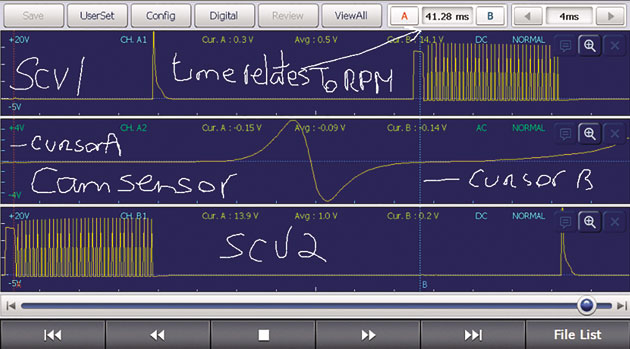
The scope image on Blue Print’s G-Scan 2
REPLACING THE SCVS
Depending on the vehicle application, certain components may need to be removed to get clear access to the valves; the following process is a removal and fitting procedure for Suction Control Valves (ADT36846C) on a 2003 Toyota RAV4 2.0 D-4D.
It should be noted that cleanliness is of paramount importance; the ingress of the smallest particle could cause the valves to malfunction. Clean around the area with brake cleaner and use an air gun to remove any small particles.
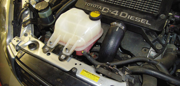
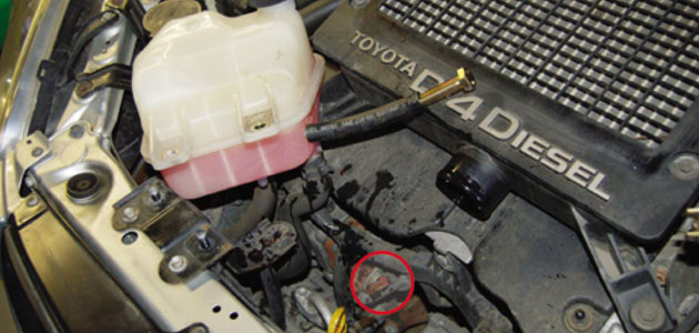
STEP 1
■ Unbolt the radiator expansion bottle (two nuts) and move it to one side to gain access to the fuel pump. You may wish to disconnect the upper hose and plug to give you more room.
■ Remove the air intake/intercooler pipe.
STEP 2
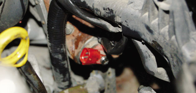
■ The fuel pump is now visible (just to the left of the starter motor). Make sure that the area around the green and red SCVs is as clean as possible to reduce the risk of debris entering the pump.
■ Disconnect the wiring connectors from the SCVs.
STEP 3
■ Remove the four SCV mounting bolts (two per valve) and then remove the two valves from the pump, making sure you note the positions of the red and green valves (red at the front).
■ Although the seals on the new valves are pre-lubricated, it is good practice to apply a little new engine oil to the seals, to reduce the risk of damage during fitting.
STEP 4
■ Ensuring the mounting area is clean install the valves carefully, making sure that they’re installed in their correct positions and that the valve flange fits flush to the pump before tightening the fixing bolts to 13Nm (10lb-ft).
■ The rest of the fitting procedure is the reverse of the removal.
■ Reset the engine DTCs using a suitable diagnostic tool (such as G-Scan or GScan 2) before road testing the vehicle.