Charles Figgins, Technical Consultant at Blue Print, looks at a poor running complaint on a Mazda MX-5 MK2
With Mazda’s MX 5 about to be reincarnated into its fourth generation, this popular two seater sports car is loved and cherished by its enthusiastic owners. It can, however, spend many months in hibernation during the winter period.
The example in this article, a MK2, was just one of those cars that was coming out of a period of non-use, with the owner noticing that their pride and joy was not performing as well as it should. After a bit of tinkering, changing the spark plugs and the air filter, they decided to take it to the garage.
A visual inspection was carried out under the bonnet to check for anything obvious. A vehicle being stored for long periods of time can be prone to rodent’s gnawing at its wiring, plug leads and even nesting in the engine bay. However, in this case everything looked to be in place and in good condition visually.
Before road testing the car I carried out a quick check for fault codes and had a glance at any data that may give me a clue to the symptoms described by the owner. This car was not equipped with an EOBD (European On-Board Diagnosis) 16 pin socket, so I had to use the Mazda 17 pin connector (Blue Print p/n BPTE1022) on the G-Scan 2 to access the information I needed.
There were three fault codes stored: air mass, engine temperature and crank position sensor, which were all down to being unplugged and being plugged back in again in the past. All codes were stored on the GScan 2 for the owner’s report before erasing. On inspecting the four pages of data provided, there was nothing obvious as the engine idled quite happily.
Hitting the road
On a road test of mixed driving, the owner’s concerns were proven to be correct. Under hard acceleration the engine did not perform as well as it should, possibly due to an engine misfire.
Diagnosis to determine where the issue stems from is not always as easy as you may think; as this car is pre-EOBD there is no misfire detection, and the ignition system is not monitored by the ECU to give you any fault codes that will point you in the right direction.
Once I’d returned to the workshop, it was time to determine the root cause of the running issue. To do this, it was necessary to consider the relationship between fuelling, compression and timing.
As the engine was running smoothly at idle and at partial load I didn’t think it was a mechanical issue, so I considered the ignition. The purpose of the ignition system is to ignite the air-fuel mixture in accordance with the demands throughout the engine’s operating range and the voltage levels that are required of it.
Diagnosis can be a complicated process of elimination; you turn from mechanic to a crime scene investigator to find the cause of a problem.
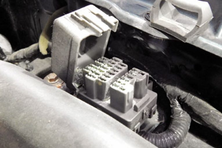
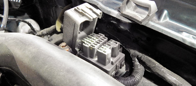
Before making a start it’s always good to consider what type of systems you’re going to work on; five minutes of research can save you hours of wasted time. I started my investigation with the ignition system. The ignition system fitted to this vehicle is a distributor less ignition, with two twin spark coils, bolted to the rear of the cylinder head on a bracket, with an integrated ignition driver end stage built in to switch the primary coils.
The engine management calculates the optimum ignition point on the basis of the stored map, for which engine speed and load are influential. Other correction variables include engine air intake and coolant temperature, along with the knock sensor feedback for any pre-ignition or detonation.
With this in mind, I browsed the serial data from the G-Scan 2 once more to see if I’d overlooked anything. It all seemed ok, so now was the time to do some component testing using the oscilloscope functions built into the G-Scan 2.
What to test?
With the ignition system design fitted to this vehicle, I had to consider which parts could be tested; these were the ignition coil supply voltage and ground, the ECU trigger pulse, primary current, secondary output voltage, and the resistance for the secondary windings and plug leads.
I started measuring the secondary ignition voltage with the G-Scan 2 oscilloscope with the HT lead adaptor (Blue Print p/n BPTE1057), mainly because of ease of access to the plug leads. On analysis of all four secondary ignition patterns at idle, all seemed OK.
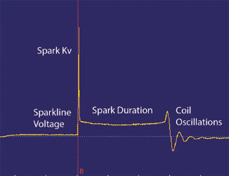
I then carried out a snap throttle test to simulate load. On opening the throttle quickly a large amount of air is induced on the induction stroke, causing a sudden increase in cylinder pressure and temperature, along with an increase in required ignition voltage, putting the ignition system under stress.
On doing this I noticed a slight misfire; measuring all four secondary voltage outputs again under this test, it was quite clear there was an issue with cylinder #4.
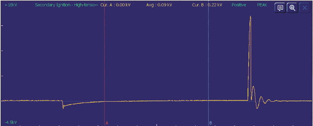
All the ignition energy was being used to jump across the spark plug gap, with nothing left to continue the spark duration. But what was causing it? Could it be as simple as a plug lead or a spark plug?
On inspection of the new spark plugs (including checking specification of the engine), they were correct. I then tested the very short plug lead of #4 for resistance which was within a tolerance of 1-5 Kilo Ohms. As I had already removed #4 plug lead, I then removed #1 plug lead and checked the secondary winding resistance (between both secondary outputs on this coil). Yet again it checked out alright, measuring between 8.2 – 12.4 Kilo Ohms. The resistance test of the secondary windings told me they were intact.
Turning my attention to the other side of the ignition coil, Mazda in its wisdom fitted the connector to both coils on top of the engine, making it nice and easy to access for testing.
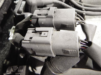
The advantage of having two separate coils is that you have another one to compare against.
Firstly I separated the connector for inspection; it was very clean and had no corrosion to cause a high resistance. I then used a break-out lead to save using back probes. I checked both coils’ supply voltage and grounds under operating conditions, and both were good. Then I checked the ECU trigger pulse and compared the signal for both coils. The pulse to the coil for cylinders #1 and #4 had a different pattern and a higher voltage.
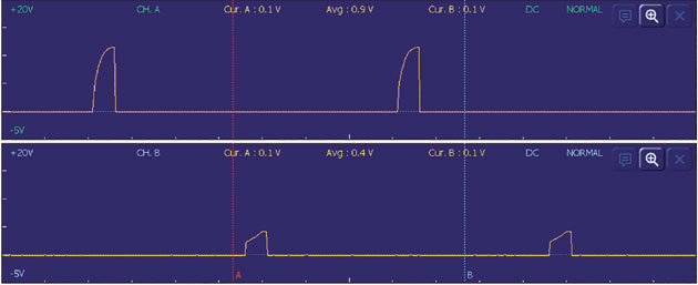
As I was measuring between the ECU and the coils, I was measuring the voltage in a series circuit between two resistances. Did this mean I was looking at a high resistance on one of the coils?
To prove this I measured the primary ignition current of both coils under load using the current clamp (Blue Print p/n BPTE1065), set to the 20A range. I measured the current on what I suspected to be the good coil for cylinders 2-3 first for reference.
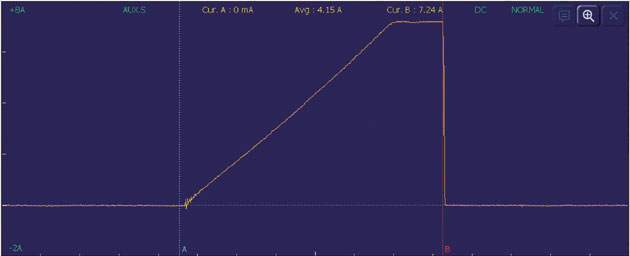
The primary current is switched by the integrated driver end stage in this application. This provides an earth path to complete the circuit for the current to flow to charge the coil. On the oscilloscope pattern it shows the current rising sharply to 7.24A; this shows that the coil is being charged quickly and is then flattening off as the coil is saturated. It is then being controlled by the ECU and switched off abruptly to ensure a very quick collapse of the magnetic field, in order to generate the secondary ignition voltage.
Measuring the coil
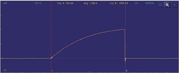
On measuring the suspected faulty coil for cylinders 1-4 the dwell time was the same, but the coil was slower to charge and it only had a peak of 4A. With this data I concluded that the misfire was due to a high resistance in the integrated driver end stage. With this affecting the primary circuit it’ll then also affect the secondary ignition voltage. Quoting ohms law: ‘If you have a high resistance, lesscurrent will flow’.
I replaced the coils on the bracket (which come as a pair), carefully removing the old plug leads; #3 plug lead was seized in the coil due to corrosion. This did not show up in any of my electrical tests, which meant it had a good contact and any resistance wasn’t affecting the secondary ignition on that cylinder. However it meant I had to replace the plug leads as well.
Diagnostics prove that even when you have diagnosed one problem, another issue sometimes comes along that you weren’t expecting.
After replacing the faulty parts and road testing, the MX 5 was back to being a fun drive. A report was prepared using the GScan 2 utility software for the enthusiastic owner, which gave them complete satisfaction that their vehicle had been diagnosed and repaired to a high standard.


