Author: Charles Figgins, Blue Print Technical Consultant
The car in question was a 350Z, which is a high performance 3.5 V6 Nissan. The owner kept experiencing the MIL (Malfunction Indicator Lamp) coming on, followed by the car going into ‘limp home mode’, which resulted in it having all the driveability of an old 1.0 Micra. As you can imagine, it wasn’t much fun to drive!
The owner said these symptoms had been going on for some time, but were intermittent. Diagnostic problems that only show themselves every now and then can be very frustrating from a workshop point of view, but the job needed to be started somewhere. As the car was driving well most of the time, and going by the only clues we had, I started with a code read of the whole car. It returned a ‘P2135 Throttle Position Sensor’ code in the engine management, ABS, and immobiliser systems. On the 350Z the immobiliser is built in to the engine ECU and it’s fitted with traction control. Before starting any testing I needed to consider what systems I was going to test and what information I had on this vehicle.

How Electronic Throttle Control systems work
Gone are the days when there was a simple cable running from the accelerator pedal to the throttle butterfly – vehicles have all gone flyby-wire in one way or another. Now you have an ECU that’s responsible for controlling the throttle valve with a motor to control the throttle valve angle; feedback is then given to the ECU by a throttle position sensor – these components together make up the Electronic Throttle Control (see image below).
To trigger this device there is an accelerator pedal position sensor, so when the driver puts their foot down the input is registered by two potentiometers. The engine ECU takes this into account, along with engine speed and temperature, plus other information from the ABS ECU. This includes feedback such as wheel spin, which causes the traction control to back the throttle off, even if the accelerator pedal is flat to the floor. The ECU then calculates the throttle valve opening which corresponds to the driver input and converts it into a signal for the throttle control motor. With this set up it becomes possible to precisely adjust the throttle valve to the required setting.

Time to start testing
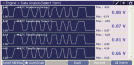
Knowing how the system worked, I graphed the data coming from the engine ECU for the throttle position sensor and the accelerator. In order to do this the ignition needs to be on, but the engine shouldn’t be running; also the vehicle has a gear neutral switch, so you must select first gear, otherwise you will not get data back from the throttle position sensor. This seems to be the case with all the other Nissan vehicles that I have tested.
On operating the accelerator pedal several times, I checked for any voltage drop outs or differences in demand between the accelerator and feedback throttle position sensors – I was looking for the sensors to be operating within a range of between 0.36V and 4.75V. If we had an incorrect voltage reading this could be the possible result of an open or short circuit, but at this stage everything looked fine. The next thing to check was the operation of the throttle valve and, again, this seemed to be OK – there was no sticking or jerky operation (see image below). Following on from this, I looked to see if there could be a wiring or connector fault; or was the ECU not giving me enough information? 
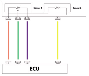
Therefore the next step was to check the voltages from the sensor to the ECU with everything still connected.

Note: All measurements were made reference to the vehicle’s ground and should not be made reference to any of the ECU’s grounds. All voltage readings given from Sensor 2 are inverted – compared with the data given earlier, the ECU changes them from a low to high voltage as displayed on the G-Scan tool. All measurements checked out correctly so the next step was to carry out a resistance check on each wire between the TPS and the ECU using volt drop testing so I could test the wiring under load. Once again, everything was fine!

Time for a road test
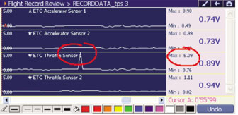
As everything was checking out under workshop conditions it was time for a road test, so I plugged the G-Scan back in and set it to ‘flight record mode’ to monitor the accelerator pedal and the throttle position sensors for a good five miles. Again the results showed nothing – this was getting very frustrating! A few miles later, as I was accelerating out of a junction and changing up from first to second, the MIL lamp came on and we went into limp home mode, just as the owner had described.

The G-Scan had recorded an open circuit on TPS Sensor 1, so we had found the reason for the MIL lamp coming on; now all we had to do was find the cause. On inspecting the connectors at the ECU and at the sensor, I found the sealing grommet missing at the sensor end (see image below). After finding a suitable replacement, checking all connections and giving them a quick clean with contact cleaner, there was a better connection. But had this fixed the problem? Before carrying out another road test, now everything was back together, I went through all the basic settings and learning procedures.

Accelerator Pedal Released Position Learning
It must be performed each time the harness connector of the accelerator pedal position sensor or ECU has been disconnected:
1. Make sure the pedal is fully released.
2. Turn ignition switch ON and wait at least 2 seconds.
3. Turn ignition switch OFF and wait at least 10 seconds.
4. Turn ignition switch ON and wait at least 2 seconds.
5. Turn ignition switch OFF and wait at least 10 seconds.
Throttle Valve Closed Position Learning
1. Make sure the pedal is fully released.
2. Turn ignition switch ON.
3. Turn ignition switch OFF and wait at least 10 seconds.
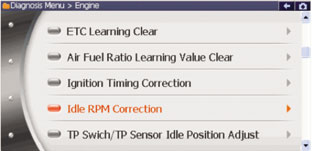
Idle Learning
Note: Make sure you carry out the above before carrying out any of the learning procedures that requires a diagnostic tool. I road tested the vehicle once more, and it was back to its high performance best; it’s amazing how such a small problem can cause so much poor drivability! Although this looked like it was going to be a time consuming job, with a well thought out diagnostic process and the right information, we could logically carry out a test routine to come to a conclusion – with a bit of help from G-Scan along the way!


