VEHICLE: 2007 Jeep Compass; VW 2.0L TDI PD Engine (Code: BLY)
TECHNICIAN: Daniel O’Connell, Auto & Marine Electrical, Ireland
DTCS: None
SYMPTOM: Misfire on one cylinder at all engine speeds. This was quite pronounced at idle
I had a customer’s 2007 Jeep Compass (European Spec) fitted with the VW 2.0l TDi PD engine. Unfortunately standard VAG software (e.g. VCDS) cannot communicate with this ECU (due to it being a Jeep). Communication via standard EOBD displayed “No Codes” although the check engine light was illuminated, and a misfire fault was present.
At this stage I needed to determine three things:
1. Are all injectors receiving a signal from the engine ECU?
2. Are all injectors drawing an equal current?
3. Which cylinder is misfiring?
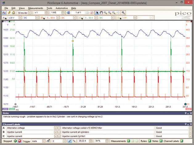
My first move was to connect Channel A to the alternator output terminal and use the Cylinder Balance test in PicoDiagnostics. With this function I was quickly able to determine that only one cylinder was at fault, as three cylinders read between 98%-100% and one cylinder read approx. 67% at 850 RPM. PicoDiagnostics was able to determine the correct engine RPM without any trouble.
I now knew that the problem lay in one cylinder but had no idea which one. In the PD engines the injectors are fed via a multiplug at the rear of the cylinder head. It is a very simple task to connect a current probe to check the current waveform of all four cylinders via the common supply wire. It is also very easy with a second current probe to get the waveform of cylinder #1.
In seconds I was able to see that all four injectors were being actuated evenly and drawing very similar currents. This quickly eliminated an electrical source potentially being responsible for the misfire. I now needed to see which cylinder was misfiring.
Normally I would check the Crankshaft Position Sensor (CKP) waveform, but a) the wire is not very accessible in this engine and, b) many of the more modern VAG PD engines use a Hall effect type CKP sensor, and magnetic coil type sensors give a much clearer indication of a misfire.
As I was already connected on Ch A to the alternator I decided to use the variation in alternator output voltage to find the misfiring cylinder. By setting the scaling of Ch A to x10, I was able to focus very clearly on the slight variations in the line voltage. By setting the low-pass filter to 400 Hz I was able to further enhance the signal and produce a very clear series of voltage readings which varied consistently with engine rotation.
Knowing that the firing order was 1-3-4-2, I could see that the misfire was in cylinder #2 and that it was a mechanical injection fault rather than an electrical one.