Oscilloscopes are an accepted part of the arsenal of diagnostic tools required for effective fault finding, however I’m still frequently asked ‘Why, Where, When, What and How’ during my training courses.
To try and answer these questions effectively I’ll focus on a series of simple case studies:
FORD TRANSIT – ACCELERATOR PEDAL PERFORMANCE WITH DTC P0121: THROTTLE/PEDAL
POSITION SENSOR/SWITCH ‘A’ CIRCUIT RANGE/PERFORMANCE
The information systems suggest that possible causes for such a fault could be the following:
■ Faulty throttle position sensor
■ Throttle position sensor harness is open or shorted
■ Throttle position sensor circuit poor electrical connection
■ Faulty Engine Control Module (ECM).
The easy option here is to simply replace the pedal (it’s a relatively common failure) but it’s much better to test the component as well as the power, ground and signal wires before condemning any parts or control modules. Obviously this may take longer than just picking up the phone and ordering the suspected part, but it is a vital step in the diagnostic process that could prevent you from making costly mistakes.
Testing the circuit
The best way of testing the complete circuit is to use an oscilloscope, but ‘Why, Where, When, What and How’ should you do this?
Older pedal position sensors use a variable resistance track that changes the voltage sent back to the module, which is then converted into a pedal position. This method uses an analogue signal, which must be converted inside the module into a digital signal for processing. Information systems would suggest connecting up a multi-meter and measuring the resistance as the pedal moved across its full range of movement. A nominal value and a tolerance would then be given.
With this type of sensor I would use an oscilloscope to test the supply voltage (normally 5V), the ground (which must be 0.1V or less) and the signal (which will sweep from 0.6V to around 4.5V). Because the ‘scope draws a picture/waveform you can then study this after the measurement has been taken and examine it for momentary signal failures, or bad sectors on the track. This is very difficult to do using a meter and a momentary glitch could well be missed due to an insufficient sampling rate.
Additional channel
Due to the nature of the input, the signal is often duplicated as a plausibility test and offers a means of failsafe operation. The duplicated signal can be inverted, starting at a high voltage and reducing as the pedal is pressed or a similar signal but at different voltage – sometimes exactly half the primary signal. This can be tested in the same way by employing an additional channel, as shown below.
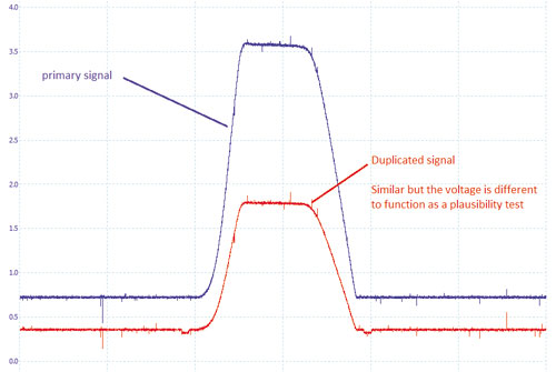
Analogue Pedal Position Sensor Trace
A good information system will identify the pins on both the sensor and the module; where you test is often down to access, but if the result obtained is incorrect you may have to test at both ends of the circuit to correctly diagnose the fault (open short circuit, module supply and ground faults).
Some newer vehicles, such as this Transit, employ a digital sensor which can be utilised by the module without any further processing of the signal. The sensor output is a fixed frequency variable duty signal and the signal switches on and off very quickly (frequency) with the on-time variable (duty cycle) directly proportional to the position of the pedal, which can be tricky to interrupt using a multi-meter.
Digital Accelerator Pedal Sensor Trace
This test shows that the power and grounds are good, as well as proving the change in pulse width.
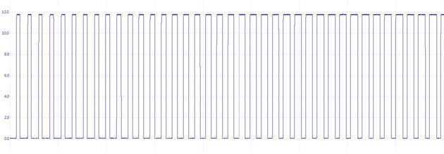
An additional measurement, using the ‘measurements’ button, adds the frequency of the signal.
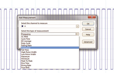
This is a simple procedure that allows you to select the channel, the type of measurement and how long to measure it for. In this case we opted for Channel A, Frequency and Whole trace. The capture below shows a frequency of 216Hz and we can see that the signal is changing 216 times a second.
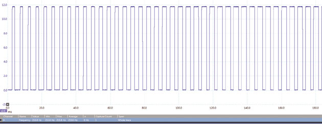
A good multi-meter doesn’t change its digital display that fast as they’ll typically refresh four times per second.
The problem occurs when checking the smooth transition from the idle position to wide open throttle and this is where the use of a built-in maths channel – to display the duty cycle – is very useful. The maths channels can be used to help interrupt signals that are otherwise difficult to decipher.
To display the Duty Cycle on a PicoScope you need to select Tools>Mathschannels>Create>Advanced>Duty>A>Next>Next>Next>Finish>Ok>. You should then end up with a trace like this:

The black trace is the duty cycle and you’ll notice the smooth transition from closed to wide open throttle. We’ve now tested the signal output, proving the frequency, duty cycle, supply and ground voltages.
I’d recommend that this test should be carried out after you fit any components to ensure the repair was successful. It will also provide a valuable addition to your waveform library.
TO SEE A VIDEO OF THIS PROCEDURE VISIT WWW.GOTBOOST.CO.UK/TRAINING. COMPLETE THE CONTACT FORM ON THE WEBSITE AND GOTBOOST WILL SEND YOU A FREE BASIC OSCILLOSCOPE GUIDE.
ARE YOU KEEPING UP? GOTBOOST CAN HELP
The automotive industry is moving at an incredible pace. Constant demand for increasing performance, comfort and reliability, all whilst producing fewer toxic emissions, has driven the industry forward over recent years.
But are YOU keeping up? When did you last invest in training for yourself or your staff?
 At GotBoost we aim to provide relevant training to help you fix modern vehicles. This will give you the edge on the competition, increase your first time fix rate, and develop the skill-set of you and your staff.
Our training is designed to be inclusive, with levels for everyone from the apprentice to the Master Technician. We want you to learn in an environment designed with the automotive industry in mind.
Most technicians don’t want endless boring lectures; they want to experience the technology from the driving seat of the equipment they will use to tackle the repairs. To help with this we’ve developed a workshop-based learning environment.
Of course you’ll have to understand the basics of the subject first, but we want you to get in the workshop and feel at ease with the tools and technology required to fix modern vehicles.
All of our courses require the learner to get ‘hands on’ so we encourage delegates to bring your their own equipment to try out their new techniques on. You’ll be shown how to do it and can then practice the skills and techniques in a supported environment. Courses include:
Oscilloscope Training: Basic, Advanced, Expert
Diesel Diagnostics: Basic, Advanced, Expert
Vehicle Electrical Systems: Basic Electrical Testing, Smart Charging, Vehicle Networks
Advanced Vehicle Networks & Coding Spark Ignition Diagnostics: Ignition Systems, Port Injection, Direct Injection
Chassis Systems: ABS & Traction Control
Motorsport: Engine Tuning Basic, Engine Tuning Advanced


