This month, Schaeffler REPXPERT Alistair Mason replaced the clutch on a 2003 Mini One, which had covered 103,000 miles. The customer reported that the clutch pedal was heavy when used.
For this repair, you need a two- post vehicle lift, engine support, transmission jack and clutch alignment tool. The scheduled labour time for this replacement is seven hours.
Step-by-step procedure
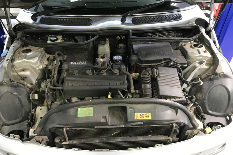
Firstly, ensure you’ve got a locking wheel bolt tool nearby before starting the repair. With the vehicle placed on the ramp, open the bonnet (see below), remove the battery cover, and then disconnect the battery.
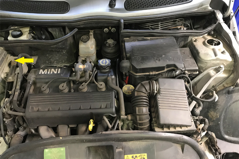
Next, detach the smaller multiplug from the engine control unit (ECU), remove the ECU from the battery box assembly that is retained by an internal clip, undo the battery box retaining bolts, and remove the battery box assembly. Remove the air filter/air box assembly, which gives good access to the top of the gearbox and bell-housing area, then unscrew the clutch slave cylinder retaining bolts and stow the slave cylinder in a safe area – don’t disconnect the hydraulic pipe! Disconnect the reverse light switch multiplug, ease off the gearchange cables from the linkage and then remove the three retaining bolts for the gearchange cable holder. Next, undo the upper bell-housing bolts and detach the rear bolt from the O/S upper engine torque arm (see below).
Next, remove the front subframe. Slacken the front wheels and the front hub nuts, raise the vehicle lift to waist height, remove the front wheels, then the hub nuts, and then tie the steering rack up on both sides to the front struts, which will hold it in position when the front subframe is removed.
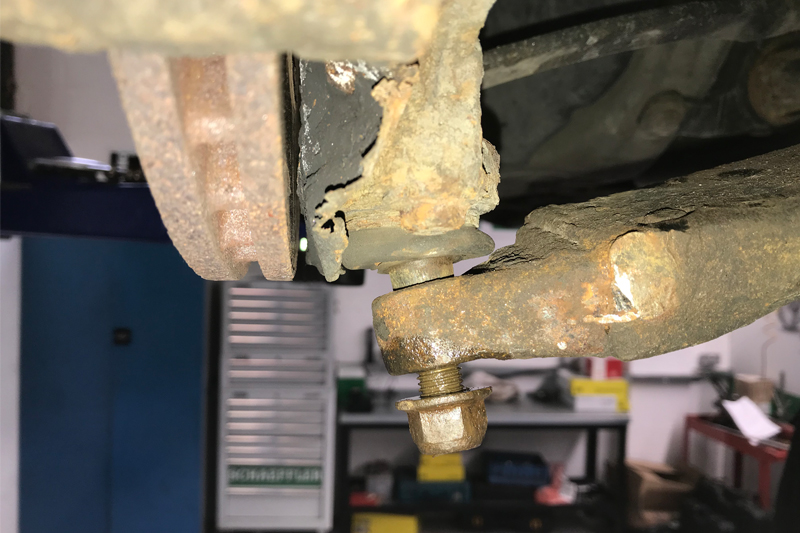
Raise the vehicle lift to gain access to the underside, detach the engine undertray, and then disconnect both bottom ball joints (see below) and the anti-roll bar links, before removing the lower engine torque arm and the subframe retaining bolts. Next, allow the subframe to lower slightly to gain access and undo the four steering rack retaining bolts. Unscrew the power steering motor mounting bolts, too.
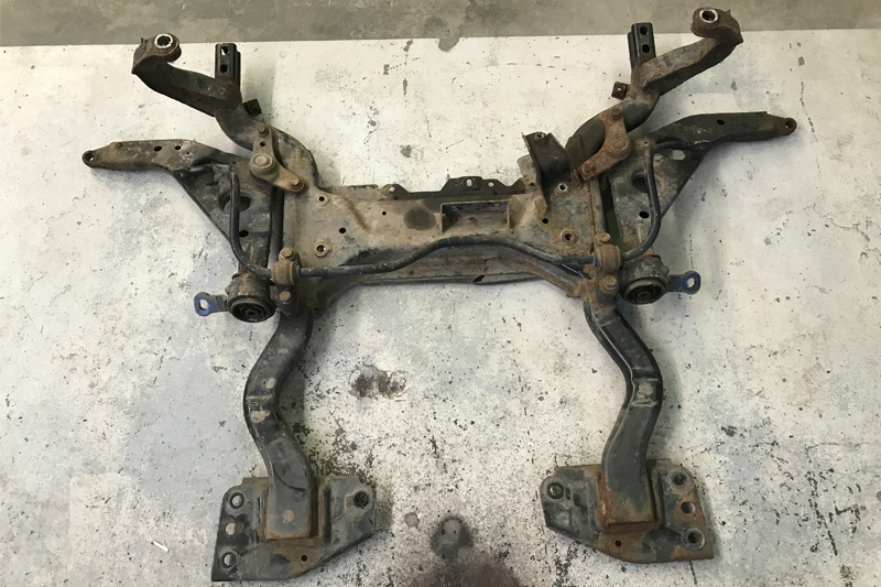
Support the subframe and ease it out of the front cross member tubes. Once free, lower and stow it out of the way (see below).
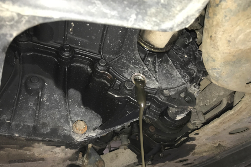
Next, drain the gearbox oil (see below), before refitting the drain plug and torqueing to the manufacturer’s specification.
With the subframe removed, the next task is to disconnect the driveshafts: undo the lower bell-housing bolts, leaving in two easily-accessible ones to retain the gearbox until ready to remove.
Support the engine, which can be done with either an engine support mounted across the inner wings, or a transmission jack/large axle stand to support the engine from the underside. In this instance, a transmission jack was used, before a second transmission jack was brought in to support the gearbox.
With the aid of a ladder/steps to gain access to the engine bay, remove the gearbox mounting. Then, from the underside of the vehicle, unscrew the two easily-accessible bell housing bolts, and ease the gearbox away from the engine and clutch assembly. Once clear, lower the transmission jack and remove the gearbox.
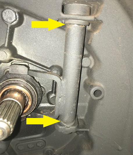
Now, detach the clutch and inspect it. In this instance, the clutch was in a serviceable condition; the release system was then inspected for correct operation and this is where the problem was identified: the bushes for the release fork had worn badly, causing the release fork to operate at a slight angle and requiring extra force to operate the clutch (see below).
With the clutch removed and the flywheel surface deglazed by an Emory cloth, it was cleaned using brake and clutch dust cleaner. The clutch plate was then mounted onto the gearbox input shaft to ensure correct fitment.
Once located, fit the new clutch using a clutch alignment tool, ensuring the clutch plate is installed correctly with either ‘Gearbox Side’ or ‘Getriebe Seite’ facing the gearbox. Install the bolts and tighten evenly and sequentially, before torqueing to the manufacturer’s specification.
With the new clutch fitted, the focus switches to the release mechanism. With new release fork bushes obtained, remove the release bearing and then knock out the retaining pin that secures the clutch arm lever to the clutch release fork. Next, remove the clutch arm lever and the clutch release fork.
Note: Be careful when trying to remove seized components from the gearbox.
The gearbox castings can be brittle and easily broken, causing an even bigger problem. On this occasion, the centre of the retaining pin was drilled, while the remainder of it was removed with a punch. The release arm lever had corroded and seized onto the clutch release fork; even a two-legged puller failed to separate the two components. At this point, some physics was applied to the job, by expanding and contracting the metal with some heat. The reverse light switch, however, was removed so as not to damage it.
Next, using an oxy-acetylene pack, heat the clutch arm lever and release the fork connection until red hot and quench with cold water. The expansion and contraction will break the corrosion/rust, and then the clutch release arm can be removed by hand.
Disconnect the clutch release fork from the bell housing and inspect for any wear. In this instance, the release arm was serviceable, so just the bushes were replaced.
Always check the release bearing guide tube for any wear, and replace if necessary, as this can cause the release bearing not to return properly. Install the release arm – here, a ‘G’ clamp was used to insert the new retaining pin into the clutch release fork and release arm lever connection.
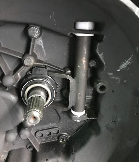
Finally, fit the new release bearing (see below). Apply a light smear of high-melting point grease to the gearbox input shaft splines and wipe off any excess.
The gearbox is now ready to be fitted; check the two alignment dowels are located correctly in the engine, and, using the transmission jack to refit the gearbox, ease into position and locate on the engine dowels. Once located, secure in position with a couple of bell housing bolts.
Reinstall all items in reverse order of removal, refill the gearbox with the correct quality and quantity of gearbox oil, and torque all bolts to the manufacturer’s specification. Once the battery has been reconnected, reset all electrical consumers as required. Finally, road test the vehicle to ensure a quality repair.


