A rear wheel bearing replacement guide for a Land Rover Freelander TD4.E
In this step-by-step tutorial we’re replacing the N/S rear wheel bearing on a 2010 Land Rover Freelander. Land Rover introduced the Freelander into its range in 1997 as a compact sports utility vehicle that was available in two and four wheel drive.
In 2002 it became Europe’s best selling 4×4, and this was updated in 2007 when the generation 2 was released, before being replaced by the Discovery Sport in 2015. This vehicle was reported to have a noise
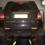
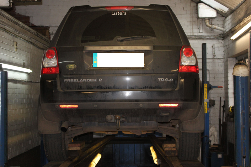
when driven above 30 mph. A road test confirmed this, and the fact that the noise was more pronounced on right hand bends indicated a failure to a near side wheel bearing. To further aid diagnosis, the vehicle
was placed on a ramp to allow the wheels to be rotated and to confirm that the near side rear wheel bearing was noisy in operation and required replacement.
The workshop equipment we used to carry out this repair was a wheel-free four post ramp, hydraulic press, a bearing press kit and a hub spreader tool.
Getting started
Before placing the vehicle on the ramp, open the new bearing kit and familiarise yourself with the replacement parts, taking note of any instructions that are supplied. You should also ensure you have the locking wheel bolt key (if required). Now place the vehicle on the ramp and slacken the hub nut and locking wheel bolt, raise the vehicle to waist height, remove the wheel and store in a safe area.
Remove the rear brake calliper and mounting as one unit (see above) and secure in a safe position. Now remove the rear brake disc; the Freelander is equipped with an inboard handbrake system which uses the internal body of the disc as a brake drum with the handbrake shoes mounted on the back plate.
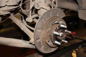
Remove the disc by removing the Torx bolt and then slide off the brake disc. Now remove the handbrake shoes (see above) by removing the two retaining pin clips and then easing the handbrake shoes off the actuation unit. At this point the handbrake shoes can be removed from the vehicle before disconnecting the handbrake cable from the actuation unit.
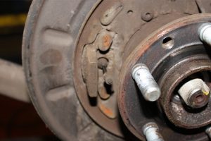
Now remove the handbrake cable from the back plate (see above); this is retained by a three prong clip (see below).
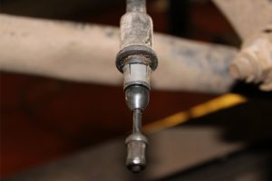
Coat the areawith some lubricating/anti-seize spray to aid removal then, in this instance, we utilised a
piece of servo vacuum pipe and worked it up the handbrake cable, through the clearance hole in the back plate, until it covered and compressed the three prongs, allowing the cable to be released from the back plate.

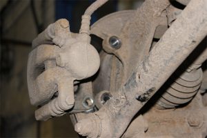
Clean around the ABS sensor and coat with some lubricating/anti-seize spray, then remove the Torx bolt and carefully ease the ASB sensor out of the hub assembly. Remove the hub nut and work the driveshaft back in the hub assembly, detach the three suspension arms from the hub assembly (see above), then
remove the pinch bolt from the upper hub assembly that clamps the hub assembly to the suspension strut.
Then insert the hub spreader tool into the pinch gap (see above), rotate the tool 90° with a breaker bar to release the hub assembly from the strut and remove in a downward direction, releasing the driveshaft
at the same time.
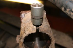
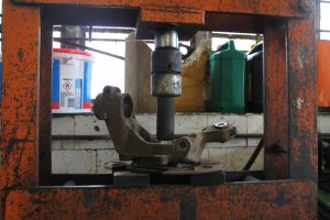
With the hub assembly removed, now replace the bearing with the use of a hydraulic press, support the outer body of the carrier and select the correct size bearing press tool to push directly on the flange body
and press out the drive flange (see below).
The inner race of the bearing may stay attached to the drive flange which can then be removed using two levers and by holding the flange in a vice.
Correct size
Now press the bearing out of the carrier. Remove the retaining clip with a small screwdriver, support the carrier in the same position on the press, select the correct size bearing press tool to press the bearing out and remove the bearing. Clean the bearing location areas (if required) and ensure the new parts are
of the same dimensions as the original parts.
Taking note of the non-verbal instructions supplied with the bearing kit, we can see that the bearing has an encoder for the ABS built in and that the bearing must be installed the correct way round. Set the carrier on the press, select the correct size bearing press tool to press on the outer race into the carrier, position the bearing correctly and press into the carrier until it reaches the stop. Now remove from the press and fit the new retaining clip.
Select the correct size bearing press tool and position under the bearing inner race to support the bearing whilst pressing in the drive flange. Position the drive flange and press in (see below) until the
shoulder of the drive flange makes firm contact with the inner race of the bearing. At this point, ensure the new bearing turns smoothly in the carrier and we’re then ready to refit the hub assembly.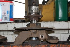
Insert the twist spreading tool into the pinch gap and open, ease the hub assembly on to the strut, locate the drive shaft and ease up to the location point. Fit and torque the pinch bolt to the upper hub assembly and refit the three suspension arms, however only tighten and torque when the weight is on the wheels to ensure the bushes are in their operating position.
Refit all parts in reverse order and torque the bolts to the manufacturer’s specifications. With the vehicle positioned back on its wheels, tighten and torque the suspension arms, hub nut and wheel bolts.
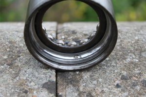
At this point we disassembled the original wheel bearing and found water ingress on the inner race and that pitting was present (see below) which was the root cause of the wheel bearing noise. A final road test to confirm that the wheel bearing noise had been rectified was carried out and that the brakes and ABS system were fault free.
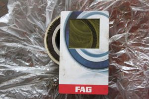
TOP TIP!
Bearing encoder reader cards can be a useful tool when replacing wheel bearings or diagnosing an
ABS fault. It is a magnetic sensitive card that show the magnetic segments contained within the bearing encoder ring to ensure the bearing is positioned correctly and that the segments are in good condition (see below). Always familiarise yourself with the nonverbal instructions contained within the box.