PICO technician Steve Smith confronts a Renault Zoe presenting worrying electric failure messages to the driver. Here, PMM finds out how Steve identified the root cause of the problem.
Manufacturer: Renault
Model: Zoe Z.E.
Year: 2013
Model code: X10
Engine code: 5AM 450
Transmission: Single speed automatic
Mileage: 16,403 miles
Failed part: 12V battery
Customer’s description
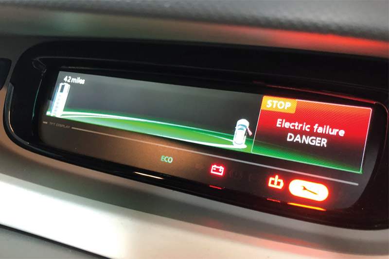
The customer reported that the following warning message appears in the instrument panel: ‘STOP: Electric failure DANGER’. This warning message would clear itself at any time and did not prevent the vehicle from driving.
Technical description
Verifying the customer complaint is an essential step in the diagnostic process, but is often a time-consuming one and isn’t always successful. On this occasion, it was noted that a different warning message would appear after the vehicle had stood for a considerable amount of time. The message ‘Check ELECTRIC system’ would be displayed in the instrument panel at the point of unlocking the vehicle with the remote key before the driver’s door was open.
It is important to note that modern vehicles may well ‘power up’ once unlocked via remote key/keyless entry systems. Therefore, be aware that ‘power up’ for electric vehicles translates to (and should be considered as) ‘vehicle live and active’.
Further quizzing of the customer revealed that the warning messages would clear themselves from the display, and therefore did not need intervention from a scan tool.
Diagnosis
With the customer complaint verified, the vehicle’s ID and specification were confirmed.
Confirmation of vehicle specification is of the utmost importance when it comes to diagnosis as there is often a temptation for customers to modify their car with fashionable accessories that lack the fundamental quality control and engineering that was intended for the vehicle. I am referring here to accessories such as parking cameras, dash cams, trackers and speed trap sensors, etc., all of which have the potential to consume the precious 12V battery reserve, or worse still, interrupt communication lines where accessories are integrated into the vehicle network. The customer confirmed no such accessories were installed to their knowledge.
The customer interview follows the four targeted, open questions below, in order to establish fact from fiction.
- How long has the problem been evident?
Periodically for 6 months - When did you first notice the problem?
During the winter months (cold weather) - Has any work been carried out on the vehicle recently?
No work other than typical maintenance when a new 12V battery was installed (replaced due to a failed routine test) - When do you experience the problem?
When the vehicle has been left standing either overnight or over a weekend
Based on the above answers I am already thinking about ‘parasitic drain’, but I do not want to assume anything.
The basic inspection confirmed no fluid leakages, no visible signs of damage to hoses, connections, wiring harnesses or indeed that favourite discovery, ‘accident repair’ (other than the new 12V battery, the vehicle looked 100% original).

A vehicle scan of all on-board control units revealed eight fault codes listed in Fig 1. To throw a curve ball, this capture used a Bosch scan tool to reveal eight fault codes, whilst a second scan (using a Launch diagnostic tool) revealed the three codes in Fig 2.

To summarise the vehicle scan, communication codes appear to be the order of the day:
- Bosch indicated three CAN codes at motor control unit (MCU)
- Launch indicated 3 CAN codes at power electric block (PEB)
Both scan tools use a different description for the same unit under the bonnet (combined motor, charger/invertor assembly), which Renault refers to as power electronics block (PEB). This is a typical hurdle to overcome with different scan tools.
Prior to diving in, taking a step back and checking for technical bulletins (recalls, campaigns, etc.) is paramount. None were relevant and so based on the vehicle history and symptoms, we can move on to possible causes.
Possible causes
- CAN network wiring
- CAN network components (ECUs)
The action plan
The action plan is predominantly governed by accessibility, probability, and cost. Based on the acquired Bosch scan data, we have five fault codes referring to either ‘CAN communication errors’ or ‘Bus faults’ (MCU 4.0 and EV ECU 4.0 respectively). Therefore, the action plan focused on CAN:
- Measurement of CAN network activity
- Wiggle testing of CAN network wiring and connectors
A variety of trim panels and under-shields were removed for access to numerous ECUs and their associated CAN wiring. The EV CAN connector at the HV battery was chosen as the measurement point for CAN circuit evaluation. Why choose such a remote connector for capturing EV CAN? My line of thinking here was the possibility of water ingress given its location under the vehicle. However, no such water damage was found.
Safety first
If a technician is determined to work on electric vehicles, it is paramount that safety is put first, along with the necessary training, PPE, and live working certification.
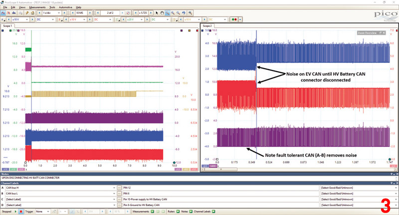
Fig 3 shows EV CAN activity captured at the HV battery whilst being charged via the electric vehicle service equipment (EVSE or Charge Station). Note that the noise present on the CAN circuit whilst the HV battery is being charged! Could this be our communication fault?
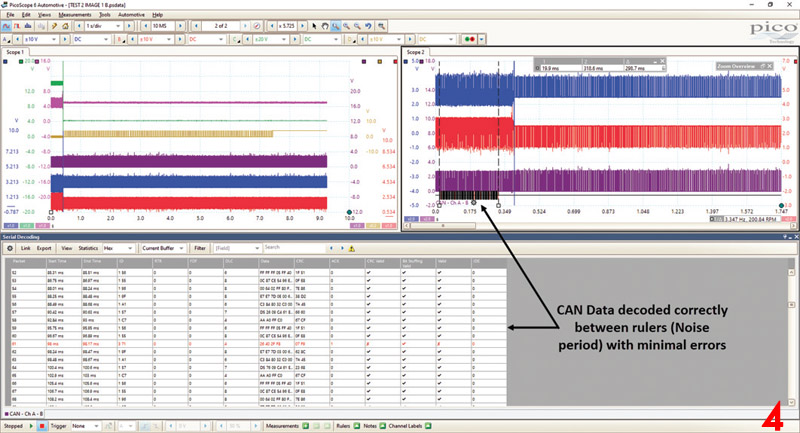
When using the math channel A-B, we could see the noise had cleared, proving once again how fault tolerant CAN has to be in such electrically noisy environments. Using the PicoScope CAN decoder (Fig 4), we went one step further and qualified that the data is decoding correctly during the ‘noise’ period with only minimal errors due to sample rate settings. The noisy CAN signal was therefore not the cause of our fault!
The wiggle test of CAN wiring and connections was next up for evaluation, and here we used the math channel A+B in conjunction with a ‘mask’. In Fig 5, we can see how the noise only intruded into the mask upon disconnection of the HV battery CAN connector (which is to be expected). Before and after disconnection, the math channel A+B remained inside the permissible ‘white’ graph area, regardless of wiring and connector manipulation.
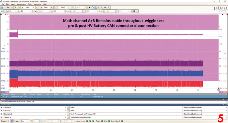
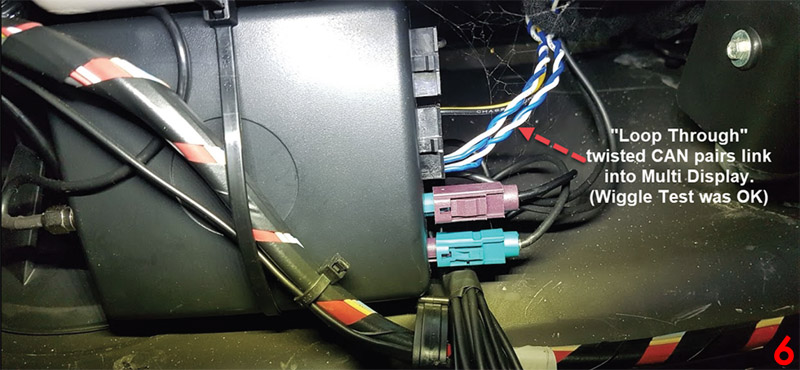
We concluded at this stage, that our CAN communication codes were not relevant to a wiring or connector failure. Whilst checking the harness routing throughout the vehicle, a tracker/telematics style device was discovered behind the fascia, which included connections into a CAN network other than the EV CAN (Fig 6). Could it be possible for the tracker to influence or disrupt messaging on the EV CAN when not directly connected to this network? It’s a question that I could not answer, but faced with a variable like this, the easiest option was to remove the device and continue to test. The customer was informed but had no knowledge that such a device was installed.
Prior to further testing, all fault codes were erased, and here I discovered another concern with generic scan tools. The CAN communication codes revealed by the Bosch tool (U1000, U1001 and U1002) could not be erased, suggesting that the faults were still present! However, they could be erased with the Launch tool, highlighting the need for ‘scan tool awareness’ when it comes to their ability to communicate on all levels with all vehicles.
Further testing and use of the vehicle over a number of weeks confirmed the inevitable, the warning messages had returned along with the codes captured using the Bosch scan tool in Fig 7.
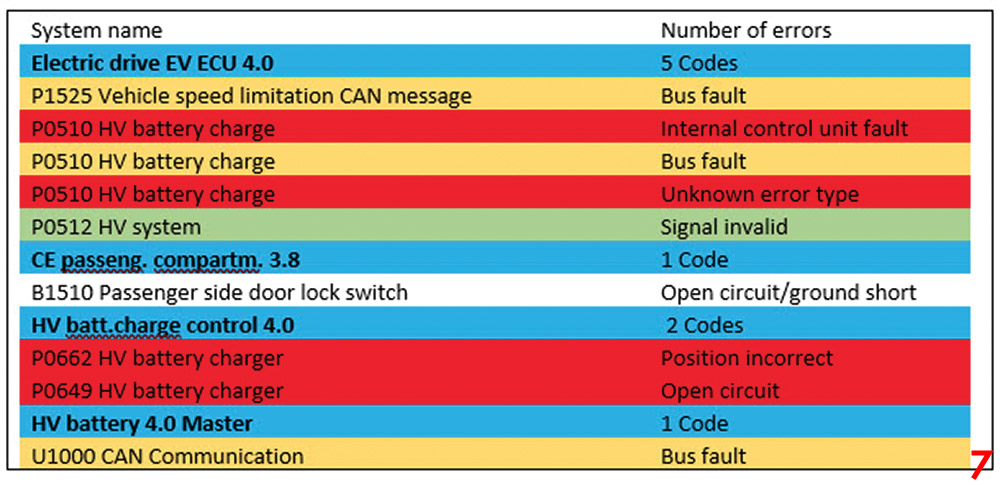
I have added colours to the second round of fault codes to indicate a number of changes that had occurred since the original vehicle scan:
- Yellow: CAN or BUS errors
- Red: Specific/descriptive codes
- Green: System codes
- White: Not relevant
The fault codes were also checked using the Launch scan tool:
EVC – five codes
- Df018 Consistent Multiplex signal for CC/SL, the data supplied to the cruise control or the speed limiter is not correct
- Df126 Battery Health Status, internal electronic fault
- Df125 Battery health status OK
- Df125 Battery health status confirm
- Df113 Pulse box signal incorrect
BMS: One code
- Df010 CAN communication no further description
Note: There are no longer communication codes for MCU (U1000, U1001 and U1002) as revealed by Bosch, and PEB (Df020, Df021 and Df022) as acquired by Launch in the initial vehicle scan. Whilst CAN/Bus faults were still present (using Bosch), the previous wiggle tests and EV CAN decoding had confirmed the integrity of the network. Focus, therefore, moved to the specific/descriptive codes.
Using multiple scan tools most certainly introduced variables in the form of ‘translations’ and ‘interpretations’ of manufacturer DTCs and component names. For example, MCU/Motor Control Unit (Bosch) and PEB/Power Electric Block (Launch) are the same component. These descriptions could have you searching for components that do not exist!
To summarise, Bosch provides an improved description of DTCs, but assigns them to ‘P’ codes (powertrain) that could be misinterpreted as generic OBD-II codes. For example, P0510 is described as HV battery charge ‘internal control unit fault’. However, P0510 OBD-II code is 02 Sensor Circuit Malfunction (Bank 2 Sensor 1). On the other hand, Launch provides unique DTCs but with minimal descriptions.
So, which tool should we use, and which codes are relevant? I have to say at this stage I did not know. Trying to establish an occurrence order to the fault codes was proving difficult and may or may not be possible using the vehicle manufacturer scan tool.
Establishing an occurrence order is often the key to finding the root cause of the original fault, allowing you to discard the numerous ‘non-relevant’ DTCs that appear as a consequence. Once again, product knowledge and familiarity of the vehicle would help here, I had neither and so an element of reverse engineering was required.
Using the Bosch scan tool, I began to sequentially disconnect a number of EV ECUs in order to determine their titles as listed in the vehicle scan report. Whilst time consuming, we discovered three key pieces of information:
- We knew the location of the ECU listed in the vehicle scan report
- We learned the title given to the relevant ECU by the scan tool manufacturer
- We discovered the ECU responsible for reporting the fault code to the scan tool
For example, disconnecting the low voltage multiplug from the HV battery revealed the ‘HV Batt. 4.0 Master’ is an ECU that resides inside the HV battery assembly (as it was no longer displayed within the vehicle scan list). This feels far more comfortable from a diagnostic point of view than ‘System Name: HV Batt. 4.0 Master (Bus Fault)’.
Armed with this new-found knowledge of all the ECU’s titles, location and codes, research was the next step. Love it or hate it Google diagnostics is nearly impossible to ignore when you have drawn a blank with your diagnostic process. After what seemed like hours of study, it appeared that there was a tenuous correlation between these OBD-II style codes listed by Bosch and the VM fault codes.
This link led to my next discovery:
- P0510 translates to Renault fault code 0510/ followed by a test number
For example:
- Renault code 0510/F1 = 12V Battery: test plan F1
- Bosch claimed P0510 = EV ECU 4.0 internal control unit fault, Bus fault & unknown fault
- P0512 translates to Renault code 0512/67 12V Battery charge control: test plan 67
- Bosch claimed P0512 = HV system signal invalid
The information above proved to be diagnostic gold and reinforces the need for manufacturer training (product knowledge) accompanied with access to technical information via the VM portal.
Thanks to Renault for allowing cost effective access to their technical information portal, I discovered when dealing with multiple DTCs you must prioritise DTC 0512. This is not such occurrence order, more of a ‘priority order’.
Recap so far
- P0512 was acquired by the Bosch scan tool
- DTC 0512: ‘Pulse box Test 67’ was described in the link to the SPEAK EV forum above
- Pulse box is reported by the Launch scan tool ‘Df113 Pulse box signal incorrect’
- Renault portal request priority is given to DTC 0512 and indicates a production improvement to the Pulse box after 30/09/13
So, what is a Pulse box and how do we diagnose it?
Results
Following the Renault test procedure, the 12V battery is to be tested prior to testing or replacing the Pulse box (interesting further discovery here, Renault DTC 0510 96 = 12V ‘Battery State of health’).
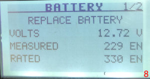
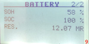
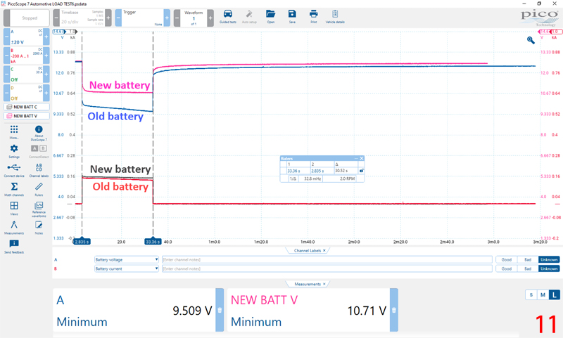
In Figs 8 & 9, we have the results of the conductance test revealing the SOH as ‘low’ for a SOC of 100%. In addition, it became apparent the battery was incorrectly specified for the vehicle.
- Failed battery specification 40 Ah EN 330 CCA
- Recommend battery specification 54 Ah 500 CCA
- The failed battery was therefore 26% below recommend capacity
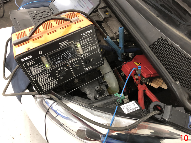
The PicoDiagnostics battery test procedure could not be applied to this vehicle as we were required to load the 12V battery using the starter motor in order to determine the characteristics of the battery. More information can be found here.
In this case, we had an EV and so no conventional starter motor to load the battery. Therefore, to qualify the performance of the new 12V battery against the old, we used PicoScope in conjunction with a traditional ‘12V battery load tester’.
In Fig 11, we plotted the volt drop and current flow from both batteries (under load conditions) where the difference in capacities were revealed. Note how the old and new 12V batteries commence the load test at similar open circuit voltages, yet the old battery continues to fall under load whilst the new battery voltage plateaus and recovers to 12 .62V post loading.
The Pulse box (confirmed post 30/09/13) is located behind the LH headlight and responsible for load testing the 12V battery prior to the customer switching to ‘Ready’ mode. Think of this as a load test across your 12V battery prior to driving vehicle (similar to cranking an engine). This is achieved by connecting the battery positive to ground via a substantial resister inside the Pulse box (protected via a Maxi fuse), whilst monitoring the voltage and current from the battery (see Fig 12).

The behaviour of the Pulse box was discovered during routine parasitic drain testing (post-12V-battery replacement), upon unlocking the vehicle with the remote key whilst the vehicle was in sleep mode (see channel D in Fig 13).
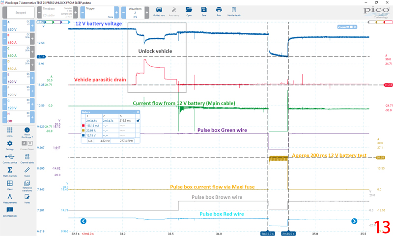
Returning to the technical description of the customer’s symptom, the warning message ‘Check ELECTRIC system’ was displayed in the instrument panel at the point of unlocking the vehicle with the remote key, before opening the driver’s door! Knowing what we found from the above capture, shortly after unlocking the vehicle, the 12V battery was load tested for approx. 200ms, and if a ‘failure’ was determined, the instrument panel would warn the driver even before entry to the vehicle! Our discovery fitted the symptom perfectly.
Confirmation of repair
Given the intermittent nature of the fault, and the conclusive evidence found above, the best course of action was to return the vehicle to the customer and to normal service/duty. After five months, there has been no return of the symptoms/faults described above, no warning messages within the instrument panel and the customer has confirmed the usage pattern remains the same.
Additional comments
To conclude, we cannot underestimate the vital role played by the 12V battery system linked to EVs. There is a mindset that because EVs have huge capacity batteries, the 12V system can be side-stepped as cranking current is no longer required and so ‘any old battery will do’.
As you can see from the carnage above, an incorrectly specified and inferior battery generated hours of study, days of work and hundreds of miles of travel.
Moving onto generic scan tools, as we know, there is no one scan tool that fits all models and using two scan tools on one vehicle threw a number of curve balls into the mix. Unfortunately, they all have their strengths and weaknesses, and with this vehicle it was necessary to use the Launch tool to erase the CAN codes discovered by BOSCH (U1000, U1001 and U1002).
By no means is this case study an assault on generic scan tool manufacturers (far from it), as without them a number of repair centers could not offer a diagnostic service. However, I hope it highlights the hurdles and variables that are introduced to diagnosis as a result of incoherent translations and explanations of DTCs and components, along with sporadic coverage of features such as read and erase fault codes.
One simple example would be ‘Battery system fail’ as a DTC description on an EV; if we had ‘Low Voltage Battery system fail’ or ‘12V Battery system fail’, this would be a huge step in the right direction.
Hindsight is a wonderful thing and I can see how I went off-piste with this case study at numerous stages. In a perfect world, product knowledge, product training, access to a dedicated VM scan tool and the relevant technical portal should have been the correct approach, but the real world is far from perfect.
Many thanks to Steve Winn from Autocare and Pete Melville at HEVRA for their invaluable support and technical input.


