In the second part of this feature, PICO Technician Steve Smith gives his all to diagnose the problem causing the engine of a 2005 Vauxhall Vectra to refuse to start. After much frustration and with a little help from the internet, Steve finds a solution.
Post intermittent cranking, we checked the fault codes again and all the previously erased fault codes had returned with multiple ECUs reporting a loss of communication with the engine ECU.
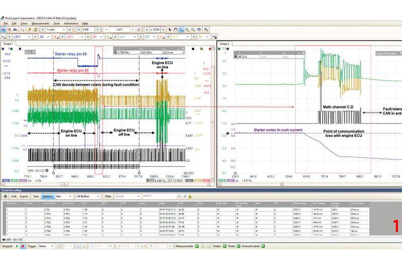
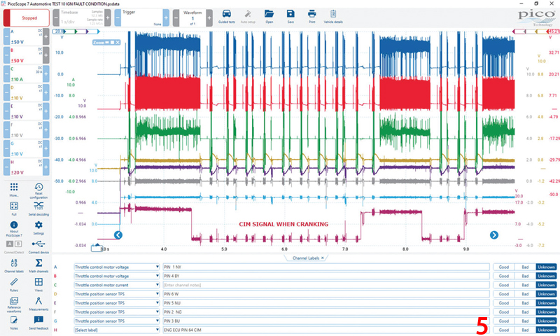
Fig. 1/main image shows how we analysed the CAN network at the engine ECU in further detail during the fault condition.
Note how the CAN noise level fell silent immediately after the momentary inrush of current into the starter motor. During this “noise-free” period of CAN activity, the engine ECU is offline until the noise level increases again after approximately 160 ms. The noise level occurs as the engine ECU momentarily appears online and begins to run through the throttle motor initialisation procedure.
This is characteristic of an engine ECU that has woken from sleep while preparing for the engine to start and is often heard when turning on the ignition of many vehicles (engine off).
Given that our engine ECU was falling offline, we could use the serial decoding feature in PicoScope to select the precise area of CAN data we wanted. This allowed for comparisons of CAN IDs before and during the fault condition (ECU on/offline) where we identified the missing CAN IDs associated with the engine ECU, reinforcing our diagnosis.
Fig. 2 shows the full list of IDs that were missing before and after the fault condition.
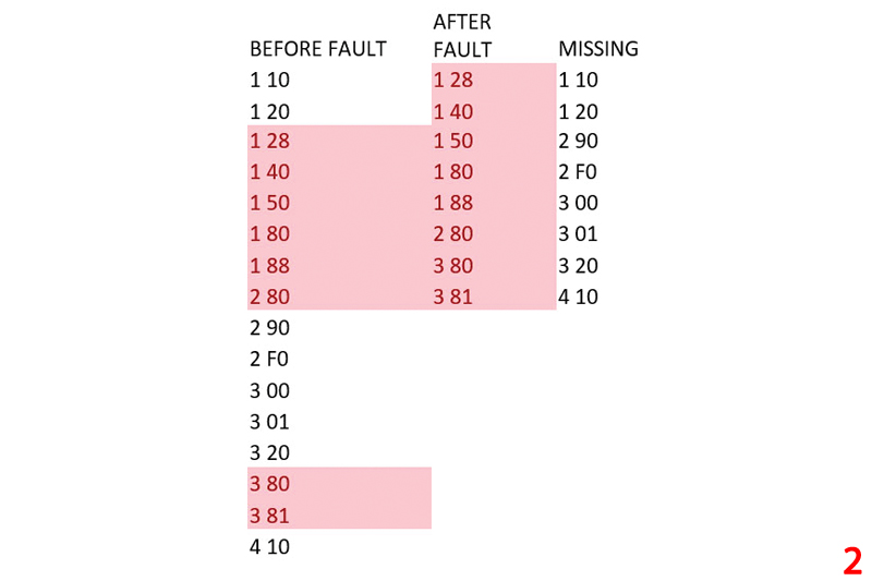
To determine if the missing IDs are entirely relevant to the engine ECU, we carried out the same procedure again without introducing the cranking fault. We captured CAN IDs with the ignition on and the engine ECU connected, then repeated the capture with the ignition on and the engine ECU disconnected. Now we could compare the missing IDs identified during this deliberate “offline” test with the missing IDs during the true fault condition.
A word to the wise when using this technique: If the ECU you are disconnecting contains a termination resistor, you will need a 120-ohm resistor to link CAN Hi to CAN Lo. This is necessary to ensure the integrity of the CAN network. Be aware that not all missing IDs originate from the engine ECU as some IDs from other ECUs may be absent because the engine ECU is offline.
To cut a long story short, we identified and confirmed several missing CAN IDs as related to the engine ECU and so we have gathered enough evidence to decide that this component needed to be replaced.
Outside help
At this point, after realising the cost of a new engine ECU, I had a moment of self-doubt, especially given the value of the car and the additional work required for the annual MOT inspection. So, when in doubt, shout for help. This is where I turned to the collective knowledge of our automotive forum.
This is not the first time I have needed a shoulder to cry on and I urge anyone who is either struggling or looking for support, to use this forum for what it is worth. If you post asking for help, please provide as much information as you can about the vehicle under test and the diagnosis process already carried out. It is also great if you can include psdata files with correctly labelled channels or good quality screenshots (ideally not a photograph of a laptop screen).
To say I struck gold with my forum post would be an understatement. Thanks to Liviu who is the Obi-Wan Kenobi (legendary Jedi Master for Vauxhall-Opel), I was able to proceed further with additional checks surrounding intermittent cranking.
If we look at the wiring diagram for this engine management from last month’s issue, the only visible “request” for cranking is via pin 85 of the starter relay or the CAN network.
Thanks to Liviu, I realised I had not taken into consideration the crank signal from the Column Integration Module (CIM). In addition, there was a concern raised about the throttle motor and control circuit with this particular generation of Vectra. Driven by Liviu’s experience, I decided to investigate both. I had this inner fear that replacing the engine ECU and not the throttle body would result in premature failure of the replacement engine ECU.
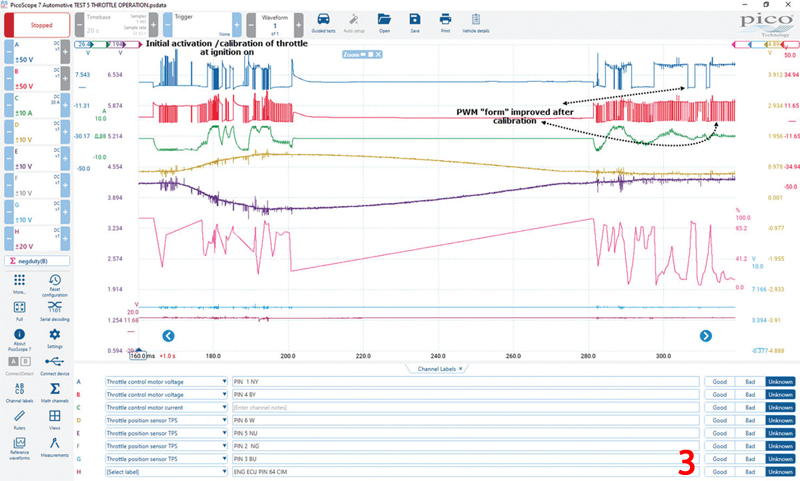
In Fig. 3, we captured the entire circuit of the throttle body during initial activation. Note the instability of the PWM signal at ignition on, which appeared to have no ground reference and “float”. (Remember that the ECU also failed to ground the starter motor relay.) This “instability” appeared to improve approximately 12 seconds after the initialisation/calibration of the throttle.
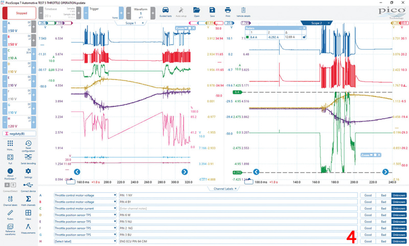
A greater concern was the sporadic throttle motor current, which appeared to fluctuate between –6 and +6 A. You can see this huge fluctuation during the initialisation of the throttle in Fig. 4.
In Fig. 5, we could see the repeated initialisation/calibration of the throttle while holding the ignition lock/switch in the cranking position. This appeared to be the Engine ECU continually resetting.
Note that the CIM signal (ECU pin 64) remained at 0 V, as expected when cranking. We, therefore, concluded that the CIM signal was correct.
So, what does this all mean? Is the engine ECU at fault or is the throttle motor faulty causing consequential damage to the ECU? Given the sporadic current flow through the throttle motor, we removed the assembly, and dismantled and inspected the commutator.
We confirmed that the commutator was serviceable with no burning, shorting or score markings and that it had sufficient brush length. We also confirmed that the rotor windings were for resistance and insulation along with the mechanical operation of the throttle butterfly and associated gears.
I hoped that we had carried out enough testing to qualify the replacement of the engine ECU. The decision was taken (rightly or wrongly) to install a second-hand ECU and a new starter motor (given the screeching during operation).
After the installation of these components, the vehicle cranked, ran and drove as normal accompanied by a sigh of relief from all involved. However, it was not over yet! Later that same evening, my colleague Kevin Ives sent a stomach-churning message: “The fault has returned”.
Back to the drawing board
Based on the logical process taken during diagnosis, what more could we have done and what could I have missed?
Sure enough, when I returned to the vehicle, we found identical symptoms and so the diagnosis began all over again. But who should be paying for it? This is the risk you take with used parts and I was grateful that I was not relying on a bonus system for my salary.
I am not going to bore you with a repeat of the above diagnosis, other than to confirm how our second-hand ECU performed identically to the original unit.
The doubt that can creep in at times like these is overwhelming – I guess it’s human nature. I am convinced the diagnosis is correct and the only “variable” is our secondhand component. After much deliberation, we replaced the ECU again, with another secondhand unit, and the vehicle cranked, ran and drove as normal.
To be sure that our fault had cleared, we subjected the engine to multiple cranking events and prolonged road tests in an attempt to reproduce the symptom. I am more than happy to say that after weeks of testing, the intermittent cranking issue was resolved (Fig. 6).
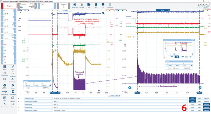
The keen-eyed reader would notice that while the engine now cranked correctly, and pin 85 of the starter motor relay was being held to ground as expected, our cranking time periodically increased.
The waveform reveals one good cranking event of around 1.2 seconds and one prolonged event of 3 seconds. There were times that cranking would continue beyond 5 seconds and the engine did not attempt to start. If reading this case study is making you think “when will it end?” you can only imagine what I was feeling before handing the vehicle back to the customer. Could we have another faulty engine ECU, but with a different symptom?
Looking closely at the waveform above, there is a clue in the prolonged cranking current as to why this engine will not start. Fig. 7 zooms into the cranking current along with the inductive crankshaft sensor signal.
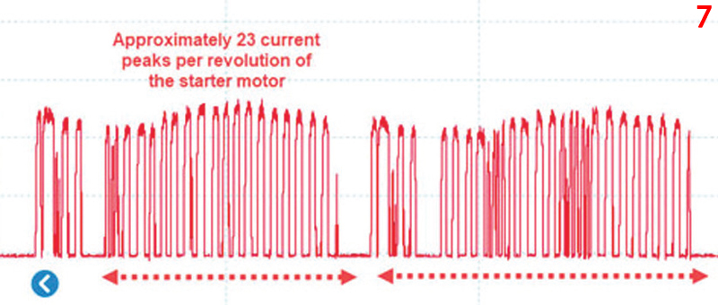
Note the prolonged cranking with very odd current peaks during the rotation of the starter motor. The current appeared to be switching on/off with periodic gaps where no current was flowing. For every revolution of the starter motor, the current was switching on and off approximately 23 times, which equates to the same number of segments on the commutator.
Thanks again to Liviu, I now know that this is often the case with new starter motors where the “bedding in” process between the brush and commutator is incomplete. An uneven patina/film coated the surface of the commutator which I must confess I have never experienced or fallen foul of until now.
It would appear to be a typical phenomenon with reconditioned starter motors for several reasons, such as the “final finish” of the brushes and commutator, material properties, environmental use, brush spring tension and alignment.
The inductive crankshaft sensor signal had been adversely affected by the electromagnetic interference (EMI) emitted from our new starter motor. Such interference may “consume” our inductive crank signal via the wiring harness where there is a capacitive link between the main starter motor positive cable and adjacent wiring, or indeed, via the engine bay environment itself. The irony in all of this is that refitting the original starter motor cured the problem.


