Testing sensors is a key part of making sure a vehicle’s emissions system is running efficiently. Here, Pico Technology provides a guide to workshop technicians using an oscilloscope to monitor emissions.
With the majority of internal combustion engines, monitoring of the emissions has long been a part of the feedback loop required to adjust fuelling, timing and ignition to ensure that combustion is as efficient as possible whilst meeting emissions regulations.
But what happens when things go wrong?
Long-term and short-term fuel trims, gas analysers and oxygen sensors are some of the tools used to determine emissions. With the introduction of additional after-treatment systems, we now have oxygen sensors (O2), oxides of nitrogen (NOX) sensors, temperature sensors and ammonia sensors all reporting back to the engine ECU. Sometimes we need to go a step further than the scan tool, which is where an oscilloscope can help.
Most after-treatment sensors will output a voltage which will vary depending on the oxygen content within the exhaust system. When catalytic converters were first introduced on petrol engines, monitoring of the converters was important in ensuring it was working correctly. Narrowband oxygen sensors were placed before (pre) and after (post) the converter and provided feedback for the engine ECU to determine the efficiency of the converter. If a fault occurs, a scope can be applied to the output of pre and post oxygen sensors in order to watch and observe what the sensors are detecting.
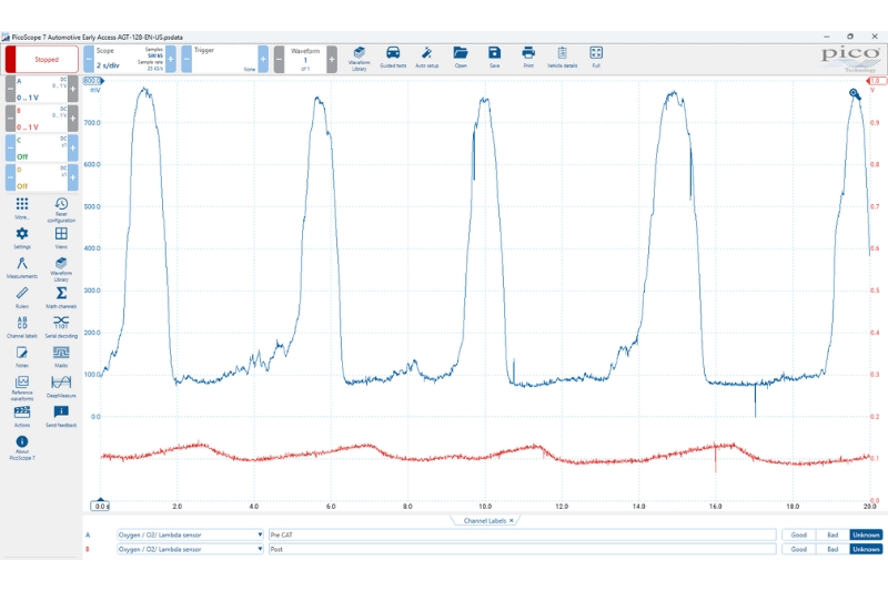
Providing everything is OK, there should be constant switching between rich and lean for the pre-cat oxygen sensor (Fig.1). This indicates the engine ECU is in control of fuelling for the engine as it adds and removes fuel to the cylinder. Providing the converter is working efficiently, the switching in the post sensor should be minimal. Should the pre and post sensor waveforms start to look the same, we can assume the converter has started to lose its efficiency and is likely to need replacement.
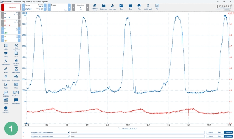
Following tighter tolerances on emissions, sensors had to evolve. These sensors look at a wider range, hence the term broadband. They measure the amount of oxygen content in the exhaust compared to the ambient and try to match the two by maintaining a fixed voltage. By ‘pumping’ oxygen in and out of a pump cell, the ECU can determine if there is a rich or lean combustion based on the reference from the measurement cell based on the amount of current required (Fig.2).
Whilst current is the actual measurement being done by the ECU, voltage and current are inherently linked therefore it is possible to see activity from this sensor by looking at the voltage output of the pump cell.

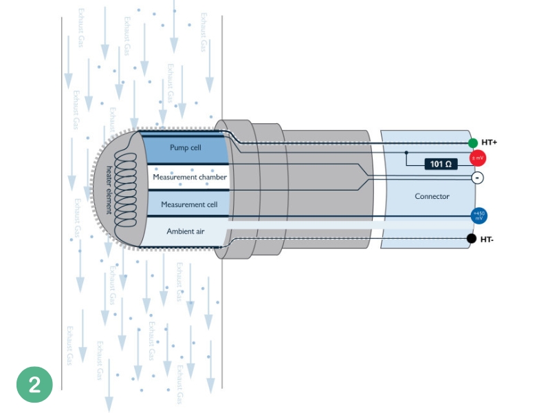
During a WOT event, we can see that the pump cell voltage drops indicating that mixture has turned rich (Fig.3). Given voltage and current are linked, we would expect current here to rise indicating the sensor is pumping oxygen into the measurement chamber. The switching of the pump cell voltage during WOT and over-run confirms the oxygen sensor to be performing correctly. The response to acceleration and deceleration of the engine should be near instant, confirming the oxygen sensor response time to be efficient.
Moving on to the modern petrol and diesel engines, oxides of nitrogen are now monitored. Typically, another converter is added to help reduce these emissions called a selective catalytic reduction catalyst. Much like the older catalytic converters, a NOX sensor is mounted before and after the converter. Unlike the previous sensors, these NOX sensors output a CAN message. Using a PicoScope, this CAN data can be decoded and with additional features to filter the data, we can now observe if the data is changing depending on the levels of NOX.
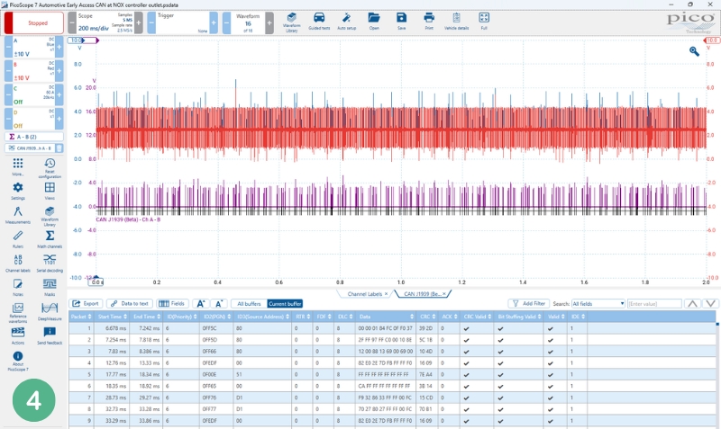
Should any information be available, we can start decoding the data fields to determine the actual values and compare these with serial data to ensure the data is correct (Fig.4).
As sensors continue to evolve and emissions controls get stricter, remember, they only ever output a signal. Providing there is a way to capture and visualise this, you can verify these sensors and their activity.


