In this Schaeffler LuK clutch feature, REPXPERT Alistair Mason is investigating a heavy clutch pedal that is also noisy in operation on a 2012 Audi A3 1.6 TDI that has covered over 125,000 miles.
Vehicle information
Manufacturer: Audi
Model: A3
Year: 2012
Engine: 1.6 TDI
Mileage: 125,000
Schedule time: 5.6 hours
Pre-diagnosis was carried out and the noise was evidently coming from the bell-housing area, the customer was advised that the gearbox needed to be removed and that the problem was most likely on the clutch release mechanism, the customer authorised the work and the vehicle was booked in.
Gearbox removal
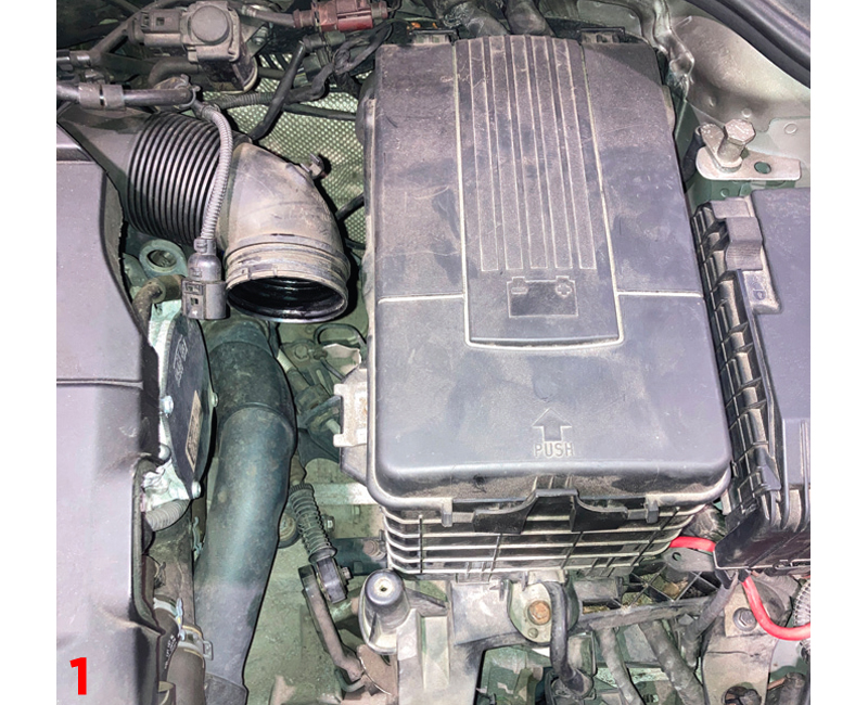
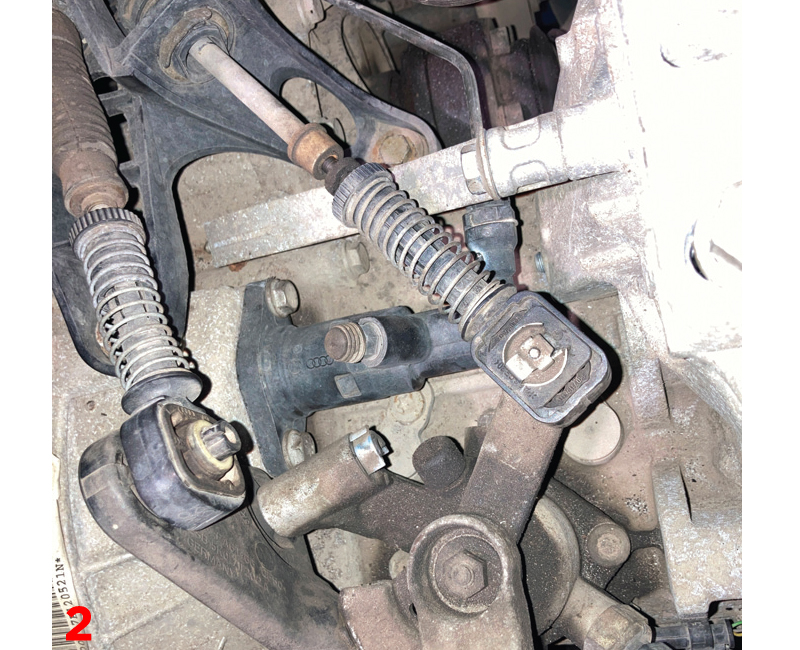
With the vehicle placed on the vehicle lift, remove the engine cover, air filter ducting, vacuum pipe, air filter assembly (Fig.1), battery and battery carrier, (Fig.2) gear change cables and cable bracket, reverse light switch connector, gearbox to mounting brace (Fig.3), slave cylinder, gearbox earth cable and top starter motor bolt and upper bell-housing bolts. Before raising the lift, slacken the N/S driveshaft hub nut as the driveshaft needs to be removed later in the repair.
Raise the vehicle lift to waist height and remove the N/S/F wheel and wheel arch liner.
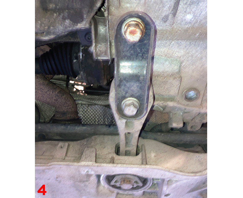
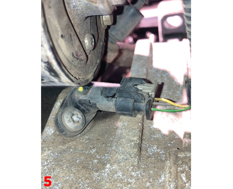
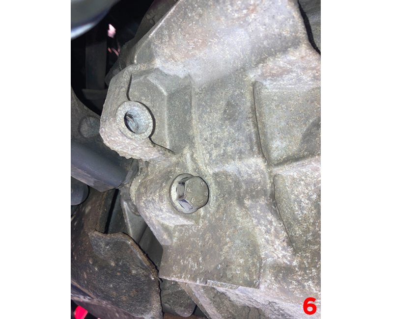
Raise the lift to gain access to the underside, remove the engine undertray, remove the lower turbo boost pipe assembly and then remove the six bolts from the N/S and O/S inner driveshaft joints, disconnect the N/S bottom ball joint, ease the N/S strut assembly out and remove the N/S driveshaft, the O/S driveshaft can be positioned away from the gearbox. Remove the gearbox pendulum mounting from the gearbox and front subframe (Fig.4), at the front of the gearbox remove the starter motor wiring and loom bracket, then the starter motor. Disconnect the gear recognition senser (Fig.5), remove the lower bell housing bolts leaving two easily accessible bell housing bolts to retain the gearbox (Fig.6).
Support the engine (the ideal equipment is a subframe attached support), remove the gearbox mounting in the N/S engine bay, lower the engine slightly to aid removal, support the gearbox with a transmission jack, remove the two easily accessible bell housing bolts, ease the gearbox away from the engine, once the gearbox input shaft is clear of the clutch, lower the transmission jack and remove the gearbox from the vehicle.
Fault identification
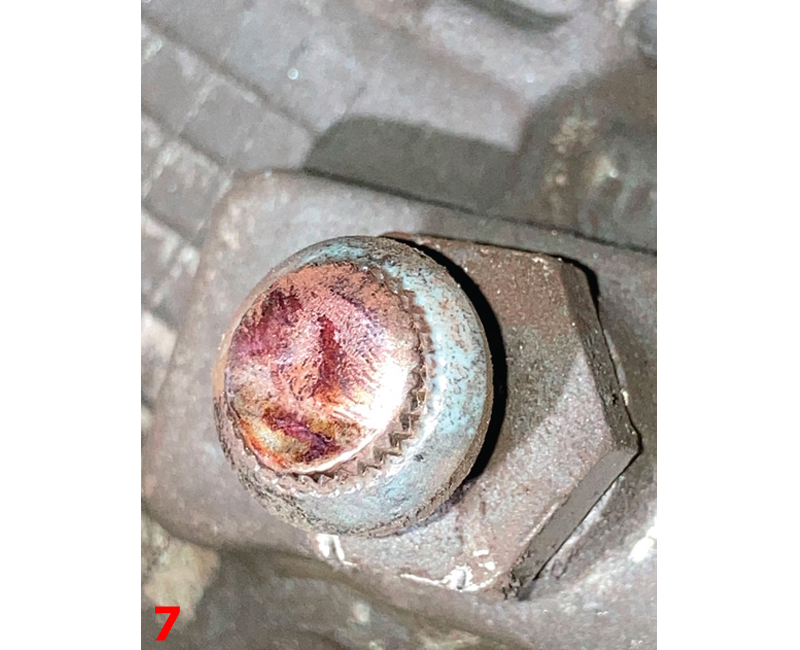
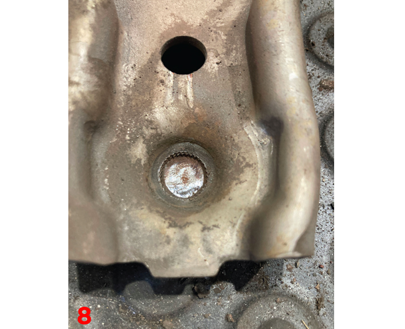
With the suspected fault being on the clutch release system, the release mechanism is removed from the bell housing, at this point the problem could be identified, the nylon on the pivot point had completely worn away so the metal release arm was pivoting on a metal pivot (Fig.7 and 8) and causing excessive wear.
At this point the clutch is removed for inspection and service life and also the dual mass flywheel is inspected for wear. As expected, being the original clutch, the clutch was at the end of its service life, the dual mass flywheel was inspected and tested for rotational free play and it is at this point we find the root souse to the problem. The dual mass flywheel had seized solid and therefore the rotational vibrations coming from the engine were not being absorbed by the flywheel and were being transmitted through the clutch and onto the release mechanism, vibrating at the pivot point and damaging the nylon on the pivot point.
With a new dual mass flywheel, clutch and pivot point priced, authorisation was given by the customer, a Scheaffler RepSet DMF is the obvious choice for this repair as it contains all parts required for the repair and the pivot point and release arm are then sourced separately.
Clutch and DMF replacement
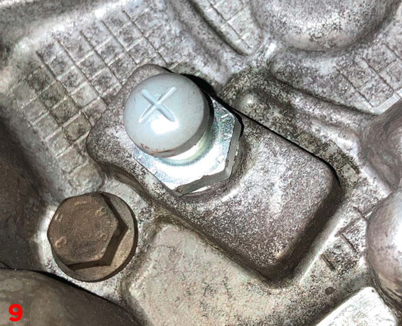
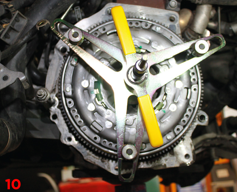
Replace the release arm pivot point that simply bolts in (Fig.9), clean the bell housing with clutch and brake dust cleaner, check the release bearing guide tube for any wear and replace if required, mount the new release arm and bearing, apply a light smear of high melting point grease to the gearbox input shaft splines and then mount the new clutch plate onto the input shaft, this will confirm the correct fitment and also evenly distribute the grease, remove the clutch plate and wipe off any excess grease. Mount the new dual mass flywheel onto the crankshaft, insert the new dual mass flywheel bolts, tighten the bolts evenly so they just “nip”, then torque to the manufacturer’s specification and then degrease the face of the flywheel with brake and clutch dust cleaner. Degrease the face of the clutch pressure plate with clutch and brake dust cleaner, using a clutch alignment tool and ensuring the clutch plate is facing the correct direction (indicated with “Gearbox side”), mount the clutch assembly onto the dual mass flywheel (Fig.10), insert the clutch bolts, tighten and torque in an even and sequential sequence.
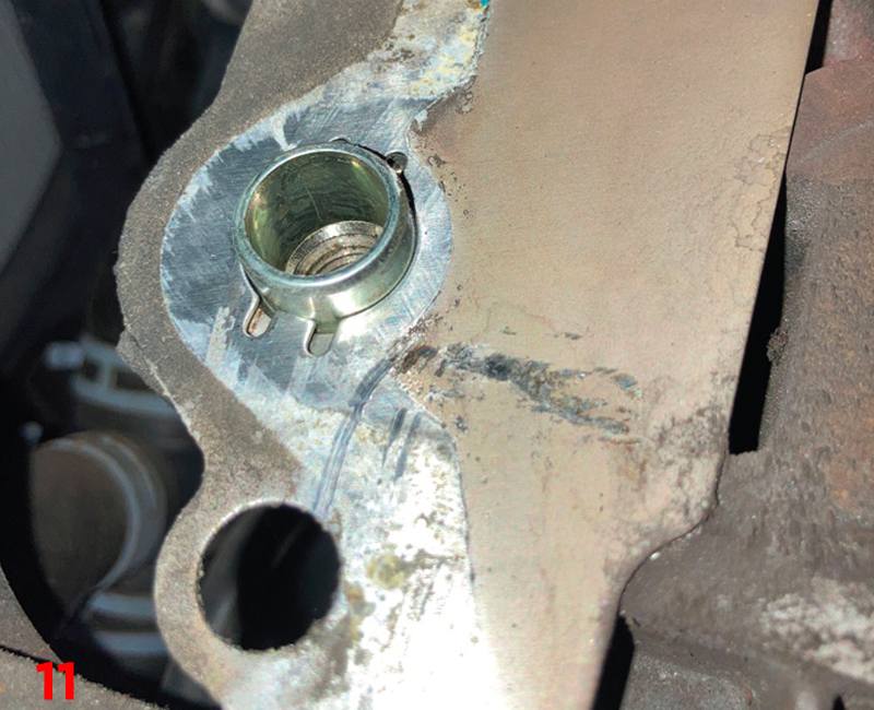
Before installing the gearbox, ensure all cables etc are clear and will not get caught during gearbox installation and that the engine to gearbox alignment dowels are installed correctly (Fig.11).
Gearbox installation
With the aid of a transmission jack, bring the gearbox close to the engine, align the gearbox and ease it into position until the gearbox is positioned on the dowels and mated to the engine, insert two easily accessible bell housing bolts and tighten.
Installation is in reverse order of removal. Before connecting the battery, is advised to disconnect the battery management connector on the negative battery terminal and to connect it after the battery has been connected, reset all electrical consumers as required and carry out a good road test to ensure a quality repair.