In the last instalment of our guide to Bosch’s KTS diagnostics software, ESI[tronic] 2.0, we looked at accessing vehicle data and delivering a full service in the face of stringent and commonplace secured diagnostic outputs. In this instalment, we are investigating the diagnosis tab and mastering actuator tests.
In this instalment, we are delving into the mastering diagnosis actuators. Under the diagnosis tab, you will find several test steps that can be particularly useful in a fault diagnosis situation. Take the actuator test function. If you are faced with an engine fault where the engine will not run to allow you to analyse the data – this function can help you quickly and easily bypass the issue (Fig.1).
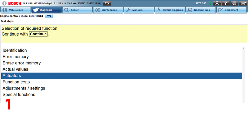
By allowing you to send a direct command to a specific component or circuit without requiring the engine to start, you can quickly and easily assess whether there is an issue with the performance or function of that specific component.
For example, if you suspect there is an issue with the engine cooling fan you can use the actuator test to command the fan to operate directly, without having to wait for the engine to reach the required temperature.
If it then doesn’t work, you have saved valuable time and can quickly progress to further tests to the fan itself. It also enables you to be far more confident in your diagnosis as you can be certain that the fan is not functioning, rather than the engine simply not reaching a temperature that would require it to cut in. As you’re in control of the test, you can check the operation of a component when you’re expecting it to happen.
Depending on what the vehicle you are working on supports, you can use these actuator tests to check many other systems – from an EGR valve in the engine management system to a headlamp bulb or an electric window regulator in a door control ECU.
Your diagnostic process
When fault-finding, the result of an actuator test can help your diagnostic process and decision making by revealing whether the fault may be on the input or output side of the circuit’s ECU. You can also simultaneously set up an oscilloscope and/or current clamp to measure the voltage and amps in the circuit when the component operates while the vehicle is static in the workshop – something that might not be practical while driving on a road test.
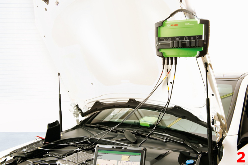
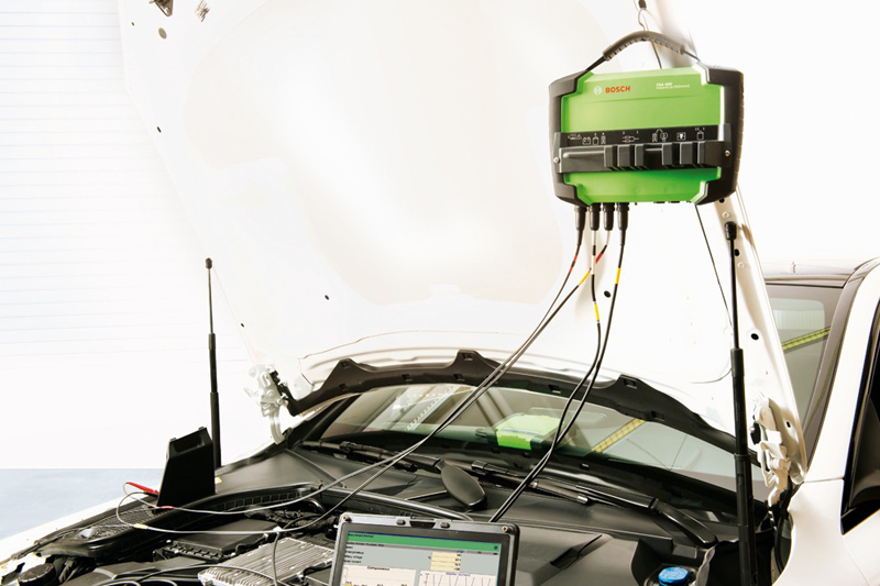
The Bosch KTS 590 has a built-in two channel oscilloscope/multi-meter in the VCI, which we will cover in a later article. For indepth, advanced system and component testing, we recommend the FSA 500 engine analyser that works in unison with ESI[tronic] 2.0 (Fig.2). A particularly useful addition where parallel testing is required.
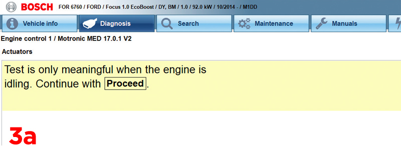
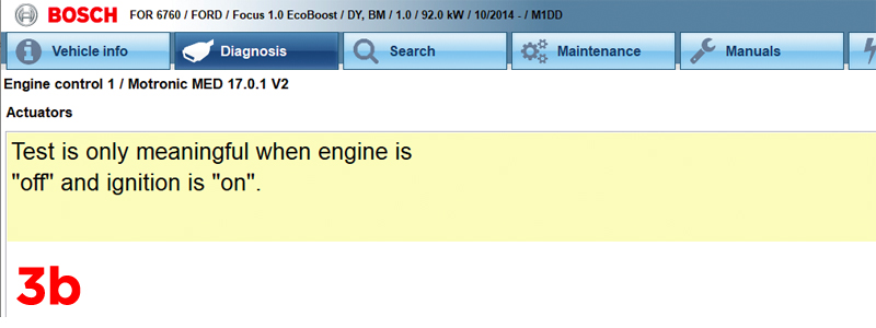
Remember, sometimes there are certain preconditions required for an actuator test to be performed successfully and you must always follow the on-screen instructions to ensure the test doesn’t fail (Fig.3a & 3b).
It’s also worth bearing in mind that if the engine is not going to be run during the test, a good battery voltage is absolutely essential. We recommend that a battery support unit, like the Bosch BAT 645, 690 or 6120 is used.
Reporting function
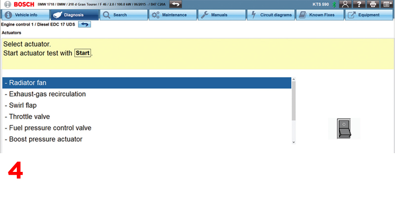
On most vehicle systems, you can pick and choose the components you want to actuate by selecting them from a list (Fig.4). Some vehicles offer a predetermined output test sequence which will operate the supported items one by one – a routine defined and designed by the manufacturer.
Most actuator tests will automatically show some relevant actual values together with the actuation process on screen to give you further evidence of the effectiveness of the test. This is beneficial when you can’t physically see or hear the component that you’re testing, such as the heated seat element. If you would prefer, you can also use the F7 (list) soft key to choose your own values to be displayed during the test.
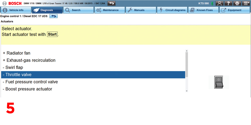
Once the test is complete, you have the option to confirm if the test was activated or not. If you click ‘Yes’ then a ‘+’ symbol will appear before that actuator name to indicate that it is activated (Fig.5). Pressing F4 when you’re finished will add the actuator results to the protocol report. You can then print off the results to show your customer as evidence of which components were tested.
Follow the steps
Your next option on the main test steps selection list is the function tests option. These diagnostic routines use a specific test plan to determine the operation state of a component or system. For instance, you will see braking tests for Bosch ABS/ESP systems that are best performed on a ‘roller brake tester’. Other function tests could be available, such as cylinder balancing or a system’s output self-test. These can aid in fault finding work and later confirming a repair to the vehicle. Next, adjustments/ settings are diagnostic procedures where stored values can be reset or changed within the control unit.
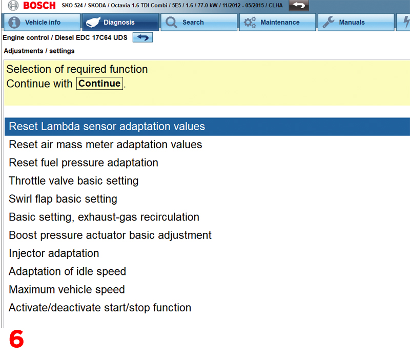
For example, this could be a service lamp reset or component adaptations, or fuel quantity adjustment if a new diesel injector has been fitted, TPMS coding if a tyre pressure sensor has been replaced, or even rain/light sensor adaptation if the windscreen has been renewed. A full selection of further options will be available for you to work through if required (Fig.6).
Finally, you can add information, such as customer and vehicle reference, to later identify the job associated with the file. The ‘actual value’ display features can be useful in diagnostics by allowing you to view and store the data from the vehicle in different ways.
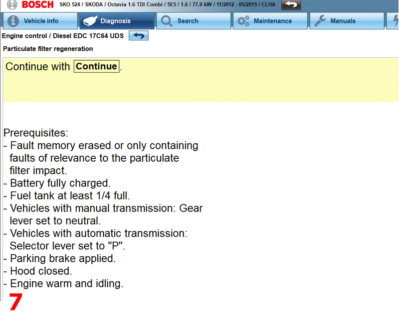
Don’t forget, certain routines will only work if the set preconditions are followed (Fig.7). In the ESI[tronic] 2.0 function tests, adjustment/settings and special functions, the pre-conditions are always stated in the information text screens that precede the start of the routine. If the KTS detects that the preconditions are not met, it will delay the start of the test and display on screen any values that are outside of the expected range.
Next instalment we’ll be using the built-in multimeter or oscilloscope functions included in the KTS vehicle communication interface.