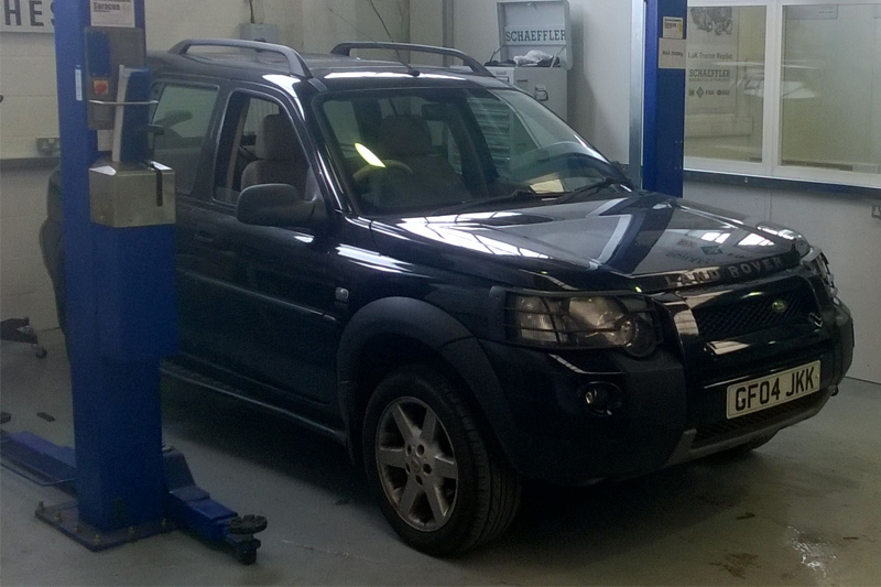
Full clutch replacement guide for a TD4 2.0 4×4 model Land Rover Freelander from the experts at Schaeffler Automotive Aftermarket.
LUK PART NUMBERS USED: DMF – 415023710; DMF BOLTS – 411002610; CLUTCH KIT REPSET PRO – 623314533
Land Rover launched the Freelander in 1997 with four engine variants – 1.8, 2.0 and 2.5 V6 petrol, as well as a 2.0 diesel, with either manual or automatic transmission. It was released as a compact SUV, with production running until 2014, before the launch of the Freelander 2 in 2006 with improved ground clearance and better off- road capabilities.
For the vehicle featured in this month’s clinic the initial fault reported was that the vehicle was difficult to get into gear and the biting point on the pedal was very low. Luckily the problem was easy to diagnose: when opening the bonnet the distinctive smell of burnt clutch was apparent and, following further questions to the customer, it was revealed that the vehicle had been used for heavy towing on the previous day.
Getting started
The ideal choice of workshop equipment required for this repair is a two-post ramp, an engine support and a transmission jack.
When checking the vehicle in, always make sure the locking wheel bolt key is available and remember that the radio code will require inputting on completion.
With the vehicle on the ramp (but not raised), starting in the engine bay, disconnect and remove the battery and the battery carrier, then remove the inlet pipes and ducting (see below). 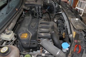
We can now gain access to the top bell housing bolts and the starter motor bolts.
Now disconnect the clutch pipe close to the gearbox by pushing in the nylon release clip at the connection. Slacken the N/S wheel bolts, raise the vehicle to waist height and then remove the N/S wheel, before raising the vehicle to full height and removing the front under trays and framework (see below).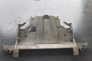
We now need to remove the centre section of the front sub-frame – also known as “the table”. This is done by disconnecting the front wishbones from the centre sub-frame, disconnecting the anti-roll bar links, disconnecting the engine stabiliser, supporting the centre sub-frame, then removing the two sub-frame mounting bolts and centre sub-frame (see below).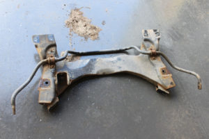
Drain the oil from the gearbox and the transfer box (Intermediate Reduction Drive unit) and, when the oil has drained, the drive shafts can be snapped out of the gearbox and IRD unit and removed by pulling outwards on the bottom wishbones. At this point we can tie back the N/S wishbone and driveshaft to give more room for the gearbox removal.
Remove the bolts from the front prop shaft joint and disconnect the prop shaft from the IRD and secure (see below). 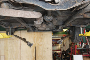
We’re now in a position to remove the IRD unit, and then the engine stabiliser mounting from the engine and the additional support bracket above. Now disconnect the coolant pipes and breather from the IRD unit, remove the four bolts that hold the IRD unit to the gearbox and then remove the IRD unit and store in a safe area (see below).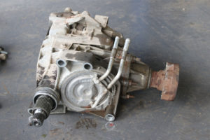
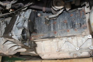
Disconnect the two ball joints from the gear linkage on the gearbox and remove the multi-plugs from the reverse light switch and speedo unit. Now remove the remaining bell housing bolts, leaving two accessible bolts to hold the gearbox, support the engine and then lower the vehicle to remove the gearbox mounting from the top of the gearbox. Raise the vehicle and remove the final two bell housing bolts, before lowering the engine slightly to allow more room. You can now remove the gearbox from the dowels and rotate the gearbox 90° clockwise, which should then give you enough clearance to remove the gearbox completely (see below).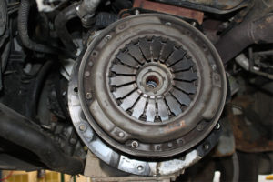
Remove the clutch assembly (in this instance over-heating was evident) and then test the dual mass flywheel with the correct tool for excess free play and rock (see below). 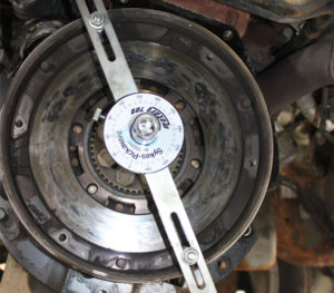
In this example we replaced the DMF as the customer had requested for this to be done. Remove the concentric slave cylinder assembly from the bell housing and clean the bell housing, before fitting the new concentric slave cylinder assembly to the gearbox; the new concentric cylinder is factory pre-filled and therefore should not require bleeding when the gearbox is installed.
Check the clutch plate fits the splines on the gearbox input shaft. This is now an ideal time to lubricate the gearbox input shaft and clutch splines with high melting point grease, wiping off any excess after the clutch plate has been checked on the splines and then replacing the clutch using a clutch alignment tool (see below).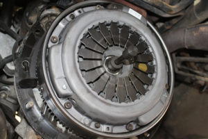
Before installing the gearbox, check that the alignment dowels are located correctly and, once checked, we’re now ready to install the gearbox. Install the gearbox in reverse order of removal, not forgetting that the gearbox and IRD unit have to be re-filled with the correct specifications and quantities of oil. Now reconnect the clutch pipe, which shouldn’t require bleeding as the system is pre-filled.
Once the vehicle is up and running, enter the radio code and carry out a road test to check the clutch, reverse lights and speedometer for correct operation.


