
The evolution of the motor car over the last 100 or so years has been punctuated by frequent design developments; some obvious and others more subtle. One thing that has remained fairly consistent is the main driver controls, including a manually applied handbrake. A manual handbrake requires significant effort from the driver to operate and this usually means large levers and movement.
There have been many design and positioning variations but the lever between the seats is arguably the most convenient for the driver. If we can replace such a mechanism with something more modest in size, with no loss of mechanical advantage, it will facilitate greater freedom in the interior design and layout of the vehicle, give the driver greater functionality and make driving easier.
Electromechanical parking brakes have been around for a while now and the purpose of this article is to give the technician an understanding of how they work.
Two types of system
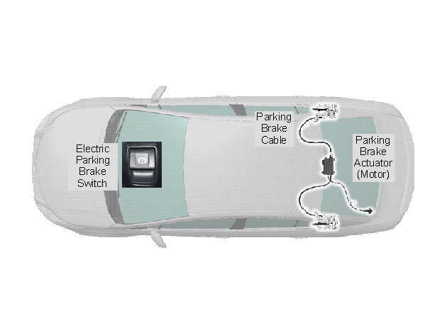
There are two distinct designs in use. The first type uses an actuator which pulls cables that are attached to conventional parking brake mechanisms. This system can be used with disc or drum handbrakes and it is often referred to as a ‘cable puller system’. It is fitted to Citroen, Renault and Toyota vehicles amongst others.
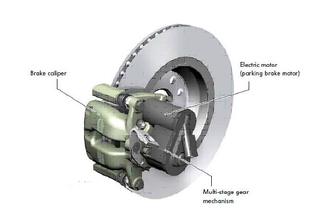
The second system is called a calliper type and uses an actuator integrated into the brake calliper. This system reduces the problems associated with cables but does increase the un-sprung mass of the suspension.
How do they work?
Both systems use electric motors and reduction mechanisms to provide the high clamping force required by the handbrake mechanism. It is how this is done that separates the two systems.
The cable puller system
The electric parking brake actuator and ECU are integral and the assembly is fitted to the rear sub-frame between the rear wheels. The electric motor incorporates a stroke sensor – which counts the number of turns the motor makes in operation – and a cable tension sensor.
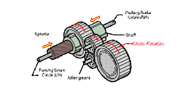
The pull effect is achieved when the motor turns the shaft. The spindle, which is prevented from turning, is pulled into the shaft by the helical grooves cut into the spindle and shaft (similar to some variable valve timing mechanisms and for those of you old enough to remember inertia starter motors, the quick start thread).
The left-hand cable is connected to the spindle and the right-hand cable to the shaft. The shaft can move freely in the driven gear so it, and the spindle, will pull in opposite directions according to the resistance felt throughout the remainder of the mechanism to the wheel stations. When the shoes/pads come into contact with drums/discs, even force will then be applied to each braked wheel, providing the necessary compensation effect (balanced braking force).
It can be seen from the diagram below that two idler gears are used. This is to increase the surface area of tooth contact between the gears to improve strength and reliability.
Note that the gear reduction mechanism (an epicyclic) is not shown on the diagram below.
After more technical advice? Click here to read the second part in this series


