

Josh Jones runs through a couple of tricky cases that were recently referred to him, and explains how good customer communication played such a vital role in getting the job done.
2007 MY Audi A3 2.0 TDI; frequent limp mode activation and EML illumination
Recently, an Audi came to me with a complaint from its owner of frequent occurrences of limp mode activation and EML illumination. The driver also felt that the vehicle lacked generally performance on demand. The car had had an analysis of its symptoms carried out at the owner’s local garage and they had correctly pointed out that the intake manifold unit (incorporating swirl flap system as shown below) was severely worn, causing a leak of charge air and that this would need to be remedied if the car was to run correctly again.
I happened to get involved with this case simply because, on receipt of the diagnosis, the owner was completely baffled by the array of options available to them in terms of a replacement manifold and, since I was a friend of a friend, the owner sought my advice before continuing with the required repair.
“As we all know, the internet can be a seriously confusing place for any consumer with a car problem, and this is where the owner of this particular car began to carry out research.”As we all know, the internet can be a seriously confusing place for any consumer with a car problem, and this is where the owner of this particular car began to carry out research on where to go next. The first few questions that came my way were: “Are you able to remove the DPF for me so I don’t have any further problems, and should I fit a manifold with no swirl flaps in?”
I explained that I was not prepared to remove any DPF from any vehicle and that in my opinion any swirl/tumble mechanism on any engine is fairly critical to its optimal performance. I have written about this conversation as I believe that the way that technicians explain diagnosed faults to customers can have a huge impact on how the repair ends up being carried out. The fact that I was able to have a face-to-face conversation with the owner of this car, using my experience as a technician to guide the customer towards the best solution for the long term performance of his car, made him feel much more at ease with spending the upwards of £500 required for a genuine replacement manifold.
I think it goes to show that most people want to do the right thing by their motor if they are guided toward the correct solution and helped with avoiding the potential pitfalls of component ‘deletes’, as it were. If I am not able to explain the relationship between a charge air leak and regular DPF blockages then what hope has the customer got of understanding what’s wrong and why it is so expensive to fix?
When an order was made for a replacement intake manifold, there was a significant delay on delivery due to back order. I guess this means that it is getting to the stage where garages will see the pictured issue overleafcommonly and if you are not doing so already, I would urge you to closely inspect this component during routine maintenance to hopefully avoid the fault getting to the stage seen in this case.
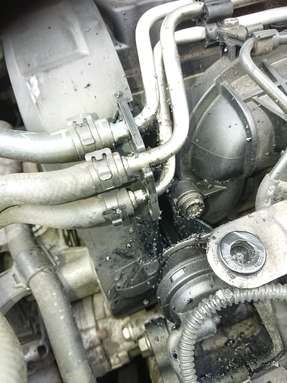
This car had suffered several consequent faults as a result of the leak and the swirl flaps being inactive, which included DPF blockages. If this issue had been picked up at service in its early stages, there would have been time to nip this problem in the bud, saving the customer time and money in the long run, in conjunction with increased revenue and customer satisfaction. I worked in a fast-fit centre during some of my apprenticeship and I will always remember my boss at the time telling me that the objective of a service is not just to carry out the specified tasks for the vehicle mileage, it is also to anticipate problems that the customer will likely encounter if action is not taken and to advise them accordingly, so the car has the best chance of driving perfectly until the next service.
2003 MY Renault Scenic 1.9dci
After having suffered an electronic park brake mechanism failure, this vehicle was brought to me after the owner’s local repairer had fitted a new parking brake module to rectify the fault. There was no EPB operation following the repair. They advised me that a configuration procedure of the new unit had been carried out via a scan tool, but they still could not get the parking brake to operate in any way.
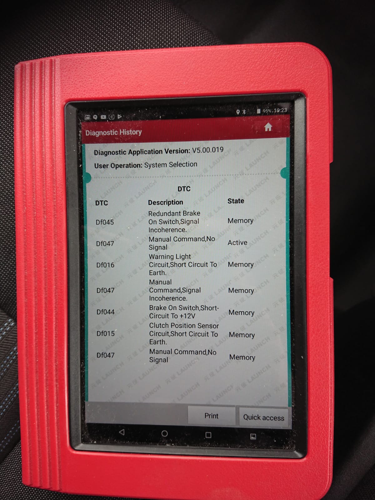
They also said that, in an effort to diagnose the problem, a new parking brake switch (driver input) had been fitted, which again yielded no results. Once I had the car in the workshop, I confirmed that there was no response at all from the switch to either activate or deactivate the parking brake, and the only visual cue that a fault was present was a flashing LED on the parking brake switch. I accessed the EPB module with my scan tool and checked for DTCs. One code was present, with the description ‘manual command signal incoherence’.
If the trouble codes were erased and the ignition cycled, the DTC would not re-trigger until the manual switch was operated, so I wanted to evaluate the operation of the switch signals to the control unit. The wiring diagram for the switch circuits shows three micro switches within the unit – one which activates when the ‘on lever’ is pulled, one that confirms the on lever is fully pulled before the off button is depressed and one more that confirms that the off button has been depressed.
From the wiring diagram, I was able to see which multiplug pins were applicable and test for the correct signals at the parking brake module, as this would confirm that the control unit was/was not getting the info required to activate the brake on demand. Two of the switch circuits were straightforward to check as they were simple on/off signals that simply pulled a reference voltage down to 0V on operation and they showed as good, but the main on switch was the one I was really interested in as this particular circuit has a simple self-diagnosis circuit built in.
The module again supplies a ref voltage to the switch, but a resistor built into the switch itself drops the circuit to 4V when connected to confirm integrity, and then to 1V when the switch is activated – simple but effective. After confirming the correct operation of all three switch signals at the control unit, I was perplexed as to why the live data stream for the switch activation was showing as inactive, even when I was pressing the switch to turn the EPB on.
I decided to run through the new module configuration process again, using my scan tool. After inputting the required info as prompted by the tool (body type, engine type, transmission etc.) the brake started to operate with no problems at all. So my mistake was to assume the initial configuration process had been a success. I can also only assume that the incomplete configuration had caused the unit to not recognise the switch input and log a DTC accordingly…lesson learned! Learning about and analysing the switch operation was certainly interesting, so for me not too much of a loss.


