
Hella Gutmann Solutions outlines the evolution of EGR valves over time, and offers some fault finding tips.
Vehicle manufacturers (VMs) across the globe have been forced to lower exhaust emissions as a result of increasingly stringent government legislation. This applies to both diesel and petrol engines, with a larger focus on diesel due to the higher level of nitrogen oxide (NOX) pollutants they emit into the atmosphere.
The exhaust gas recirculation (EGR) system helps to moderate NOX emissions produced in the combustion chamber when the engine’s combustion temperature is high by introducing a proportion of its exhaust gas into the intake air, thus lowering the temperature. The EGR system becomes active in diesel engines when the exhaust gas reaches 450 ̊C, whereas it is 650 ̊C in petrol applications. In addition, there are both internal and external EGR methods.
With the internal EGR, the exhaust emissions and the intake air are mixed inside the combustion chamber. On all four-stroke engines, this is achieved by the system-related overlap between the inlet and exhaust valves. The design means the EGR rate is very low and can only be influenced to a limited extent. It is only since the development of variable valve control that it has been possible to actively influence the recirculation rate in a load and rpm dependent manner. In contrast, external EGR is carried out using an additional line between the exhaust manifold/exhaust pipe and the intake manifold, as well as the EGR valve.
EGR valve evolution
The first systems were controlled by a poppet valve, which was opened or closed by a vacuum cell (pneumatic drive). The induction pipe pressure served as a control variable for the vacuum cell. Therefore, the position of the poppet valve was dependent on the engine’s operating state.
In order to further influence the EGR rate, pneumatic check valves, pressure limiting valves and delay valves were installed. Some systems also factor in the exhaust gas back pressure as a control pressure for the vacuum cell. In some operating states, the EGR is switched off entirely. This is enabled by the installation of electrical change-over valves in the control line. Despite these possibilities for influencing the recirculation rate, the system was always dependent on the engine’s load state and the associated induction pipe vacuum for controlling the vacuum cell.
In order to meet the requirements placed on modern engines independently of the induction pipe vacuum, electrical drives for the EGR valves were developed. Sensors for detecting the valve position were also integrated. In addition to stepper motors, linear solenoids and rotary solenoids, DC motors are now also used as electrical drives.
The control valve has also changed, with rotary slide valves and flap valves now also used. Although the EGR valve is the most important, the system also requires several other elements such as thermovalves and a pressure transducer, as well as exhaust gas temperature, oxygen and exhaust gas pressure sensors.
EGR system fault finding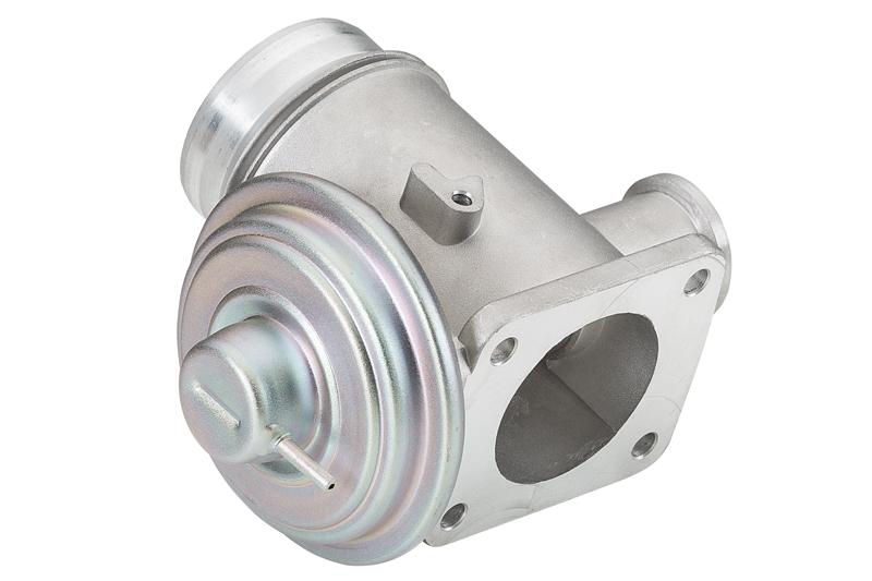
Due to the high loads it has to withstand, the EGR valve is generally the most likely source of faults. Over time, oil, mist and soot from the exhaust emissions impede the valve, gradually reducing the size of the opening until it becomes completely restricted. This causes a steady reduction in the quantity of exhaust gas recirculated, affecting exhaust emissions.
In other cases, the hose for the vacuum can trigger faults. However, the lack of vacuum could also be caused by a faulty pressure transducer or thermovalve.
There are several ways of checking the EGR system. Systems that aren’t capable of running self-diagnostics can be checked using a multimeter, a manual vacuum pump and a digital thermometer.
Before technicians start running complex tests, they should conduct a visual inspection to ensure all vacuum lines are leak-tight, correctly connected, and routed without kinks. Similarly, they should check that all of the electrical connections on the pressure transducer and change-over switch are correctly connected, with the cables in good condition. Finally, the EGR valve and its connected lines must be tested for leaks.
If no defects are found during the visual inspection, EGR systems with diagnostic capability can be checked using a suitable diagnostic unit.
The key to an effective diagnosis is to check components that only have an indirect influence on the EGR system. If the control unit receives an incorrect value from the air- mass sensor, then the quantity of exhaust emissions to be recirculated will also be calculated incorrectly. This can worsen the emission values and cause major problems with engine operation.
It is also possible that no faults are displayed during diagnostics and the actuator test also does not indicate a problem. In this case, the valve may be highly contaminated, and the valve no longer provides the opening required by the control unit. It is therefore advisable to remove the EGR valve and check for contamination. Following the replacement of any component in the EGR system, the fault memory must be deleted using the mega macs tool and if necessary, the adaptation values restored to the VMs specified settings. Finally, read out the fault memory again to ensure there are no further problems.


