
These days, Exhaust Gas Recirculation (EGR) systems are commonplace on a wide range of petrol and diesel engines in an attempt to reduce nitrogen oxide exhaust emissions. Due to the harsh operating environment the EGR valves operate in, they are prone to problems that range from sticking to complete failure due to heat and carbon fouling.
Failures are manifested by poor running at idle and low load, poor fuel consumption and reduced engine performance, or even limp mode engine operation with associated fault codes and MIL light.
EGR valves are commonly a simple two-wire solenoid valve, driven open by a pulsed ECU signal and returned closed by spring pressure. When faults occur it is due to the valve sticking partially open or binding, so the ECU signal is no longer able to open it.
Why use an EGR Tester?
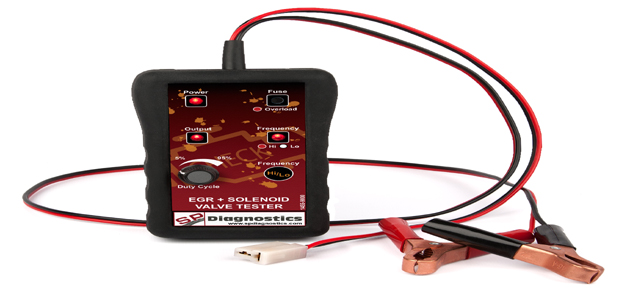
An EGR Tester, such as the new EGR and Solenoid Valve Tester from SP Diagnostics, is able to drive the valve under manual control. Although this can be done with the valve in-situ, it is of limited benefit due to the fact that the user is unable to see how the valve is behaving. Removal of the valve is beneficial in that it allows for visual inspection and cleaning if required.
The valve mechanism may be either a single integrated valve/solenoid unit or a vacuum operated valve controlled by a remote solenoid valve attached by a short hose. Both systems can be tested, but a vacuum hand pump will be required for the remote type valve to physically operate the valve whilst driving the remote solenoid with the tester. Access problems aside, the valve is usually easy to remove with just a few bolts detached in order to release it.
The EGR and Solenoid Valve Tester from SP Diagnostics helps the technician test the integrity of EGR valves and other 12V solenoids, such as vacuum solenoids, boost pressure control valves and actuators, petrol injectors, carbon canisters and even relays.
Due to the tool’s variable frequency, EGR valves can either be cycled to ensure correct operation or to clean it during its cyclic mode. In high frequency mode, the valve can be opened progressively, allowing more efficient manual cleaning.
Although EGR valves can be activated in situ, SP Diagnostics believes that removal of the EGR before testing is essential to visually confirm full and correct operation, with the added benefit of full access for thorough cleaning.
How it works
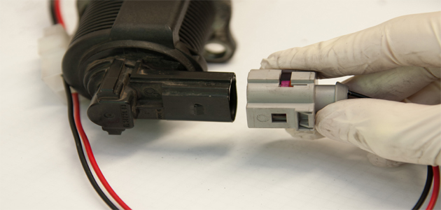
The EGR Tester is simply connected either via a dedicated connector for the particular valve – if available – or with universal push-on terminals sized to suit the pins in the valve connector. If the valve has a position sensor, the connector will have multiple pins – often five or six – so care needs to be taken to connect to the correct pins.
Reference to wiring diagrams for the vehicle, or measurement with a multimeter to identify the coil terminals will assist with this. The resistance measured across the coil terminals will generally be in the region of 4-12 ohms and will be isolated from all other pins.
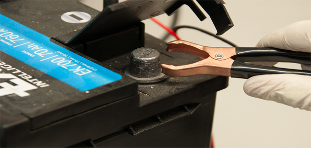
With the tester connected to the valve, attach the tester crocodile power clips to a 12V source – most conveniently the car battery to power the tester. The Power LED will illuminate to confirm connection. Two modes of operation are available, selectable by pressing the Hi/Lo frequency button:
1. “Lo” frequency
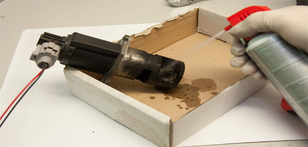
“Lo” frequency selection drives the valve continuously to fully open and closed positions at a rate of approximately once-a-second. This is a useful setting to use for a cleaning cycle to exercise the valve whilst spraying in a cleaning agent, or submerged in an ultrasonic cleaning bath, for example. It will also quickly indicate visually if the valve is opening and closing fully and in a timely fashion.
The “Duty Cycle” rotary control varies the proportion of open to closed time during the one second cycle.
2. “Hi” frequency
“Hi” frequency selection drives the valve progressively from the closed to open position in response to the setting of the rotary “Duty Cycle” control. The valve will progressively open as the duty is increased and close as it is reduced. This will confirm smooth valve operation from fully closed to fully open positions, which should occur progressively without any sticky or hesitant movement.
LED indicators will confirm which mode is selected in response to the “Hi/Lo” button and also the tester ‘Output’ status – on or off in the case of Lo mode, and varying intensity in Hi mode in response to increasing duty cycle setting.
In the event of an overload due to a short circuit or a faulty valve drawing too much current from the tester, the output will disconnect and the ‘Overload’ LED will illuminate to indicate this. The overload trip will automatically reset when the overload condition is removed.
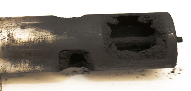
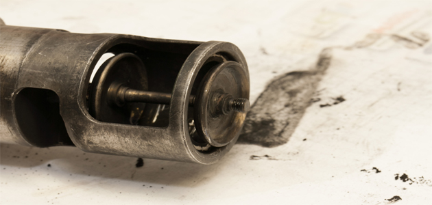
Cleaning may return a carbon fouled valve to normal operating condition, but if not then it will need to be replaced. The EGR Tester allows the user to make that decision confidently without incurring unnecessary cost of replacement.
In the case of a valve with integral position sensing, it is obviously possible that the feedback sensing element may be faulty. Once confident that the valve is physically opening correctly, this can usually be checked with suitable diagnostic equipment to read the position value from the ECU system.
1. Connect the valve
2. Attach the tester crocodile clips to a 12V source
3. The valve can now be tested

4. The technician can now determine whether the valve needs replacing or can simply be cleaned.
Before After
Product features:
• Operating voltage = 9-15V
• Switching current >2A
• Low frequency switching (for ON-OFF opening) approx. 1 per second (1Hz)
• High frequency switching (for progressive opening) = approx. 400Hz
• Switching Duty Cycle variable of 5%-95%
• Push-button to select frequency
• Rotary control to vary output switching Duty Cycle
• Overload protection for excessive current draw provided by self-resetting trip
• LED indicators for Power, Output Status, Frequency Selection and Overload
• ABS plastic case with protective and ergonomic rubber over-boot
• Large crocodile clip battery power connections
• Interchangeable valve connection adapter leads


