ACtronics explains why, when it comes to replacing ABS processors, specialist assistance is always advisable.
Generally, when it comes to ABS units, you will find that most customers’ cars will either have an ATE or a Bosch unit on board. These two manufacturers have tied in almost all of the mainstream manufacturers. Rather unsurprisingly, each combination of vehicle and ABS unit has its own common faults, so the same unit is subject to different common issues depending on what vehicle it is in.
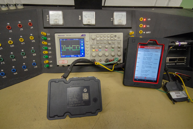
For example, on BMWs post-2005, you will likely find the ATE MK61. The most common fault codes we see with the ABS are ‘5DF0 – Hydraulic unit pump motor’ and ‘5DF1 – Hydraulic unit pump motor connector faulty’. When these fault codes appear, it is usually the ABS unit that is at fault. The pump motors on the ABS are constantly working and moving dozens of times a second.
This is to maintain constant pressure on the braking system in order to control the flow to one or more of the calipers. If the pump motors become worn or seized, the ABS will fail to operate correctly, which will usually result in both fault codes appearing. Volkswagen Group vehicles will commonly use the same ABS unit, but will often have different faults from the BMWs. Usually the ABS ECU itself is found to be faulty on VAG vehicles, with fault codes ‘01130 – ABS Operation: Implausible Signal’ or ‘16352 – Control Module – Electrical Error’ a common occurrence. When these fault codes are present, we have seen defective components on the Printed Circuit Board (PCB). These defective components are usually in the form of one or more processors that have failed and would need replacing.
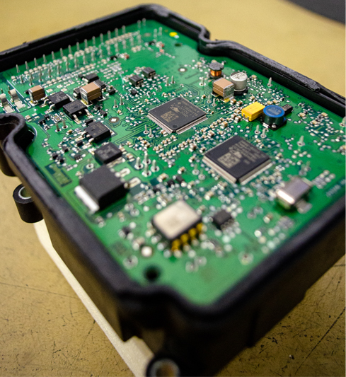
ABS units usually have two processors that control the ECU: the ‘main brain’ of the unit and what is commonly known as an Input/Output (I/O) processor. This I/O processor is given the information from the main processor and will distribute the information to the various components on the PCB. However, the I/O processor is designed to take the strain when the ECU becomes defective, in order to protect the main processor.
Replacing these processors is not a simple task and will require specialist work, due to the fact that every processor is attached to the PCB with at least 128 connections. A large heat sink causes everything to cool down very quickly during soldering. Removing and soldering a processor is therefore not possible without a special process where the cooling down is no longer a problem. Our R&D team has found a good solution for this.
As with all units that are sent to us, we will require full diagnosis and testing to be done prior to sending, which will include the testing and checking of wiring, sensors and fuses.


