
The Double Clutch Gearbox is a semi-automatic transmission manufactured by VAG. This type of transmission has been utilised across the range of VAG models since being introduced in 2004 and it has proven to be a very popular choice for consumers and vehicles.
Unfortunately many garages in the UK IAM are not aware that this transmission can be easily diagnosed and repaired with a little extra knowledge and very little cost.
It may surprise many that the VAG Double Clutch Gearbox actually uses a Dual Mass Flywheel (DMF) which can be diagnosed in a similar manner to a manual gearbox. They are simple to replace and the parts are available from all local LuK supplying factors. To show how easy this is to do, in this month’s clutch clinic we will be looking at the replacement of the DMF on a Mk5 VW Golf GT TDi with the DQ250 wet transmission.
Check data sticker
Before commencing with the repair ensure that the vehicle you are working on does have a DQ250 type gearbox as this procedure does differ for other variations. The gearbox code can be identified on the data sticker in the handbook or in the boot. If you are unsure please call the LuK Technical Hotline who will be able to advise you accordingly.
Before starting the repair you will need to acquire a gearbox fluid re-filler tool which screws into the oil container and allows the oil to be pushed into the gearbox. You will also need a transmission jack, an engine support cradle and a long axle stand. A twopost ramp was used in this example however a four-post ramp may not provide enough clearance. For safety reasons its considered best practice to disconnect the battery earth lead before commencing work. If the vehicle has alloy wheels it may be fitted with antitheft wheel bolts, so make sure you have the key before you start.
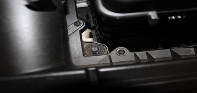
Open the bonnet and lift off the engine cover. Remove the battery cover and disconnect the battery terminals. Undo the clamp holding the battery in place and lift the battery out of the tray. Disconnect the Mass Air-Flow sensor (MAF) and the air filter housing attached to the front slam panel. Undo the single allen key bolt (pictured below) securing the air filter housing and release the clips securing the assembly to the inlet manifold.
Disconnect any attached breathers and remove the entire air filter housing by pulling sharply upwards, allowing the rubber fixings to release.
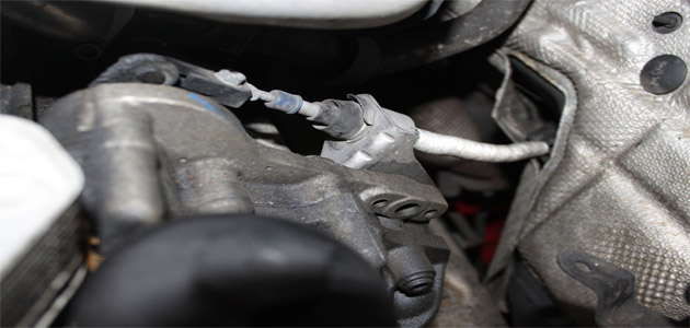
tery surround and undo the fixing bolts in the base of the battery tray. Release any attached wiring harnesses and lift out the tray. Disconnect the gear linkage (pictured below) cable by marking the adjuster mechanism position and undoing the nut.
Remove the large circlip retaining the cable onto the securing bracket and release the cable and stow it to one side.
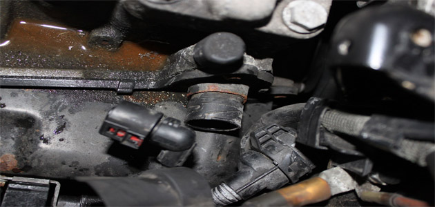
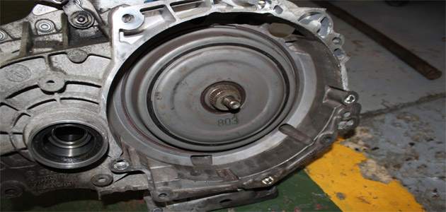
Remove the earth connection from the gearbox mounting bolt and clamp the coolant pipes connected to the cooler on top of the gearbox and disconnect them. Remove the electrical connections on the starter motor and both bolts securing it in place, allowing it to be removed. Disconnect the large round electrical connecter attached to the gearbox opposite the breather (pictured below).
Undo the bolts securing the coolant pipes for the oil cooler and stow them to one side. Use the engine cradle to support the weight of the engine and undo the upper bell-housing bolts. The gearbox mounting bracket can now be removed.
Raise the vehicle and remove the nearside front wheel and the wheel arch liner. Undo the nearside front driveshaft bolt and remove the lower arm nuts and release the lower arm. Undo the bolts securing the flanges to both sides of the gearbox and remove the nearside drive shaft. Unclip and remove the large intercooler pipe in front of the radiator and undo the single nut securing the electrical connectors (pictured below) attached to the side of the gearbox.

Drain the gearbox fluid and separate the two gearbox flanges by undoing the allen key (pictured below) bolt in the centre.
If the flanges are not removed the one attached to the long shaft fouls the DMF when trying to remove the gearbox and it makes it very difficult to remove. Undo the gearbox steady bar and the lower bell housing bolts and, while using the gearbox stand, lower the transmission to the floor.
Inspect the DMF
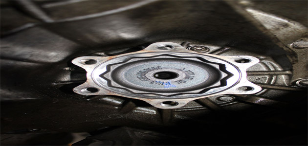
With the gearbox removed, visually check the DMF (pictured below) for signs of excessive grease loss.
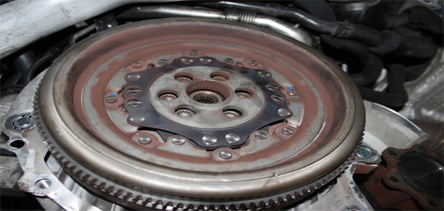
The splines at the centre on the DMF locate onto the splines on the clutch attached to the gearbox and the condition of these splines should be checked for excessive wear. These types of DMF can’t be tested in the same manner as a conventional DMF so only a visual and audible inspection is required.
No reprogramming is needed to replace the DMF, simply unbolt the old unit and install the new one. Check the spigot bearing in the crankshaft for wear and replace if required. The seals on the clutch centre shaft and around the outer lip (pictured below) need to be checked for leaks and no fluid should be evident inside the bell-housing.
Before refitting the gearbox, make sure the locating dowels are in place and not damaged. Refit any that have become dislodged and refit the gearbox. Make sure the gearbox bell housing bolts are secured before lowering the jack. Refitting is the reverse of the removal.


